A robot timing budget is not a spreadsheet you fill in after the system is built.
It is the contract that decides whether a sensor measurement is still fresh enough to influence motion, whether a ROS 2 callback is late enough to invalidate a command, whether a controller output should be admitted to hardware, and whether the microcontroller should keep executing or fall back to a safer local behavior.
Without that contract, teams usually debug timing by vibes: “the robot feels laggy”, “the planner sometimes hesitates”, “the controller is probably fine”, “the camera is only 30 Hz”, or “the Jetson should be fast enough.”
That is not engineering. A cyber-physical system needs numbers.
This guide is a practical way to build a sensor-to-actuator timing budget for a ROS 2 robot. It connects the system architecture from ROS 2 architecture patterns that scale, the kernel-level concerns in real-time Linux for robotics, the MCU boundary in micro-ROS on Jetson, and the evidence workflow from ROS 2 logs and rosbags for AI-assisted robot debugging.
The goal is simple:
Every actuator command should be traceable to sensor data, robot state, and controller decisions that are fresh enough for the motion being attempted.
Key takeaways
- A sensor-to-actuator timing budget defines the maximum allowed age, latency, jitter, and deadline miss behavior from physical measurement to physical command.
- The important number is not only average latency. For robots, the dangerous values are worst-case latency, jitter, stale state, callback backlog, missed deadlines, and command age at the hardware boundary.
- ROS 2 QoS deadline, lifespan, liveliness, tracing, lifecycle state, diagnostics, and rosbag evidence should be part of the timing contract, not only debugging tools.
- High-rate control should usually live close to the actuator: motor controller, microcontroller, or real-time control layer. ROS 2 can supervise, estimate, plan, and send bounded setpoints, but it should not hide unbounded timing in the motor loop.
- A good timing budget includes rejection rules: when to drop stale sensor data, reject an old command, hold the last safe setpoint, enter a degraded mode, or trigger a safe stop.
- The budget must be measured under load: perception running, logging enabled, network active, GPU inference loaded, and the robot executing realistic motion.
Citation-ready answer
A sensor-to-actuator timing budget for a ROS 2 robot is a written and measured contract that bounds how old sensor data may be, how long each processing stage may take, how much jitter is acceptable, and when a command becomes too stale to reach an actuator. It should include sensor sampling age, driver latency, ROS 2 transport and callback latency, TF freshness, state-estimation delay, planner and controller periods, microcontroller handoff time, actuator response delay, watchdog timeouts, and fallback behavior for missed deadlines. The budget is valid only after it is measured on the real robot under realistic compute, network, logging, and motion load.
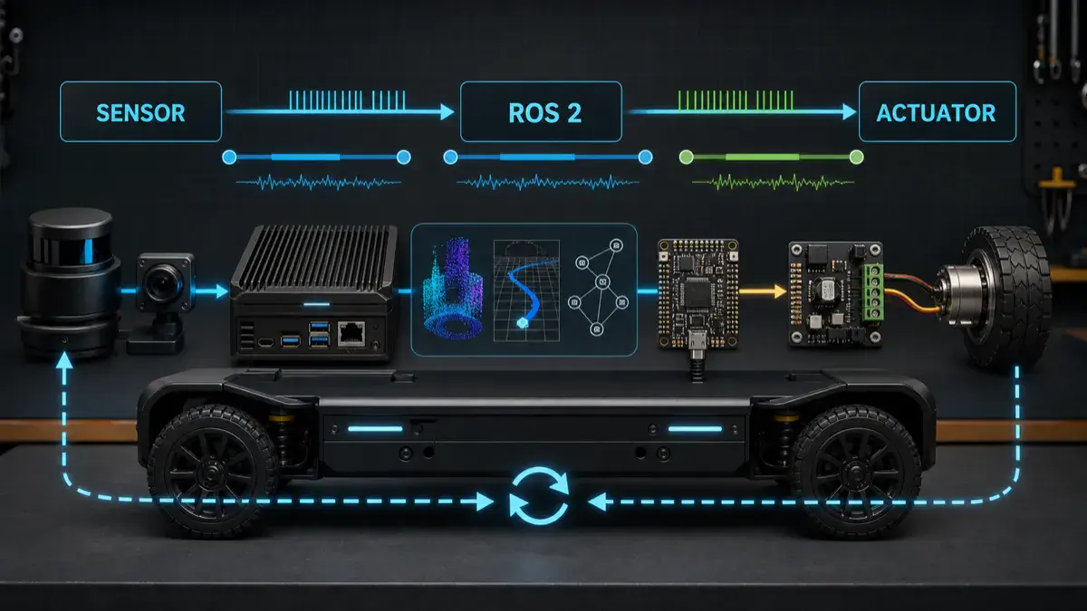
Start with the physical loop, not the software graph
The software graph is not the control loop.
The physical loop is:
1 | world changes |
The latency budget belongs to this whole chain.
If you only measure one node, one callback, or one model inference call, you can still miss the real failure. A command may be computed quickly from stale input. A planner may publish on time while TF is late. A controller may run at 100 Hz while the motor driver applies commands with 40 ms of bus and firmware delay. A camera pipeline may have low average latency but large tail latency when GPU memory is under pressure.
For robots, “fast most of the time” is not a safety property.
The timing-budget table
Start with one table per control path. For a mobile robot, create one for base velocity. For a manipulator, create one for joint trajectory execution. For a voice-controlled robot, separate the conversational path from the motion-admission path instead of pretending speech latency and actuator authority are the same thing.
Here is a reference budget for a small ROS 2 mobile robot using LiDAR, wheel odometry, IMU, local planning, and a microcontroller bridge.
| Stage | Example rate or bound | What to measure | Failure rule |
|---|---|---|---|
| IMU sample | 200-1000 Hz | sample timestamp, driver publish latency, dropped samples | Ignore samples older than estimator window |
| Wheel encoder update | 50-500 Hz | MCU sample time, transport delay, sequence gaps | Hold local velocity if encoder stream is stale |
| LiDAR scan | 5-30 Hz | scan start time, scan end time, driver delay | Do not use old obstacle data for fast motion |
| TF lookup | 50-200 Hz effective | transform age, lookup failure, extrapolation error | Reject control step if required transform is stale |
| State estimation | 30-200 Hz | input age, output age, covariance growth | Enter cautious or hold mode if state is stale |
| Local planner | 5-50 Hz | planning duration, input age, horizon freshness | Do not execute path from stale costmap/state |
| Controller | 50-200 Hz in ROS 2, higher near motor | loop duration, period jitter, command age | Drop command if age exceeds command freshness limit |
| ROS 2 to MCU handoff | 50-200 Hz setpoints | transport latency, sequence gaps, watchdog heartbeat | MCU falls back if heartbeat or command expires |
| Motor control | 500 Hz-20 kHz | firmware loop period, PWM/current loop jitter | Keep inside motor controller or MCU |
| Actuator response | device-specific | step response, braking time, mechanical lag | Include in stopping-distance and safety envelope |
The numbers are not universal. A warehouse AMR, balancing robot, inspection rover, quadruped, lab arm, and cable-driven mechanism all need different budgets.
The method is universal: each row needs a rate, an age limit, a measurement method, and a failure rule.
Freshness beats throughput
Robotics teams often optimize throughput first. That is understandable for perception and AI workloads, but control paths care more about freshness.
A 30 Hz camera frame that arrives 180 ms late is not equivalent to a fresh 30 Hz camera frame. A reliable ROS 2 topic that queues ten old messages can be worse than a best-effort topic that drops old samples and gives the estimator the newest measurement. A controller callback that executes every 10 ms can still produce unsafe output if it is using a transform from the wrong time.
The ROS 2 documentation on QoS settings is useful here because deadline, lifespan, liveliness, reliability, history, and depth are timing tools, not just middleware options.
The practical questions are:
| Question | ROS 2 concept | Engineering decision |
|---|---|---|
| How often must this topic publish? | Deadline | Raise an event if expected updates stop |
| How old can a message be before it is useless? | Lifespan | Drop expired data instead of processing stale state |
| Should old messages accumulate? | History and depth | Keep last 1 for many control inputs; avoid stale queues |
| Is the newest sample better than guaranteed delivery? | Reliability | Use best effort for some high-rate sensors when freshness matters |
| Is this publisher still alive? | Liveliness and lease duration | Treat lost liveliness as a fault input |
| Should late joiners receive old data? | Durability | Usually no for live sensor/control streams |
Do not blindly copy QoS defaults. A default queue depth of 10 may be harmless for low-rate state, but it can be a hidden latency buffer for fast feedback paths.
Separate four timing numbers
A useful budget separates four numbers that are often confused:
| Number | Meaning | Why it matters |
|---|---|---|
| Period | How often a task should run | Defines the expected rhythm of the loop |
| Latency | Time from input event to output result | Decides reaction delay |
| Jitter | Variation in period or latency | Breaks controller assumptions and synchronization |
| Age | How old the data is when used | Decides whether the command is based on reality |
Average latency is the least interesting number. A robot can tolerate a slightly slower but bounded path better than a fast path with unbounded spikes.
For a control-facing path, write the acceptance rule like this:
1 | Use this command only if: |
Those numbers are examples, not defaults. The point is that the validator needs explicit thresholds.
Where ROS 2 should stop and the microcontroller should begin
ROS 2 is excellent for distributed robot software: state estimation, planning, actions, lifecycle, diagnostics, logging, visualization, and supervision. It is not automatically the right place for the fastest hardware loops.
The closer the decision gets to motor current, PWM, encoder sampling, braking, or a hard interlock, the stronger the case for a microcontroller, motor controller, safety controller, or real-time firmware loop.
The timing split I usually use is:
| Layer | Typical time scale | Good responsibilities | Bad responsibilities |
|---|---|---|---|
| AI or operator layer | seconds | intent, explanation, high-level task request | raw motion or safety state |
| ROS 2 supervisor | 50 ms-seconds | state, actions, validation, diagnostics, mode control | hard motor timing |
| ROS 2 controller | 5-20 ms when carefully designed | bounded setpoints, trajectory following, local control | unbounded blocking, heavy inference |
| microcontroller | 0.1-10 ms | encoder reads, watchdogs, PID, PWM, local interlocks | semantic planning |
| motor driver | microseconds-ms | current loop, protection, low-level commutation | global autonomy |
This is the same authority boundary behind splitting authority between an LLM, ROS 2, and a microcontroller. Timing is one reason the split exists.
The official micro-ROS execution-management documentation is also relevant because it explicitly discusses sense-plan-act chains, deterministic execution, callback order, real-time guarantees, and microcontroller support. That is the right mental model: when timing matters, callback order and bounded execution become architecture, not implementation detail.
TF freshness is part of the budget
Many timing bugs look like geometry bugs.
If the transform tree is stale, the robot can compute a perfectly reasonable command in the wrong frame or at the wrong time. The ROS 2 tf2 documentation describes tf2 as a time-buffered frame tree. That time dimension is not optional.
For every motion path, define:
- which frames are required,
- which node owns each transform,
- the maximum allowed transform age,
- whether extrapolation is allowed,
- what happens when lookup fails,
- whether the command should be rejected, clamped, or delayed.
Example:
1 | For base velocity commands: |
This is also why timing budgets help with sensor fusion drift debugging. Drift is often blamed on the filter, but the root cause can be timestamp skew, transform age, or stale input data.
Measure the path under real load
A timing budget is only useful if it survives the actual robot workload.
Measure while the robot is doing the thing you care about:
- perception running,
- TF active,
- state estimation active,
- planner and controller active,
- logs and rosbag recording enabled,
- GPU inference loaded if the robot uses edge AI,
- network connected if the robot depends on it,
- operator interface active,
- safety monitors active,
- realistic motion commands executing.
ROS 2 tracing is the right tool when callback timing matters. The official ros2_tracing tutorial shows how to collect trace events and analyze callback durations. Use rosbag and structured logs for system evidence, but use tracing when you need callback-level timing.
At minimum, record these fields:
| Evidence | Why it matters |
|---|---|
| Message header timestamp | When the measurement claims it was sampled |
| Receive timestamp | When the node actually saw it |
| Callback start and end | Whether processing time fits the budget |
| Output publish timestamp | When the next stage became available |
| Sequence number | Whether messages were dropped, duplicated, or reordered |
| TF lookup time and transform stamp | Whether geometry was fresh |
| QoS deadline/liveliness events | Whether a topic violated its timing contract |
| MCU command sequence and heartbeat | Whether hardware handoff is fresh |
| Actuator feedback timestamp | Whether the physical response arrived in time |
Do not measure only on an idle desk. Measure during thermal load, CPU load, GPU load, network noise, and long-duration operation. Timing failures often appear after the demo has been running long enough for fans, memory pressure, logs, and background processes to matter.
Failure modes to look for
Most timing failures fall into a small set of patterns.
| Failure mode | Symptom | Usual cause | Better response |
|---|---|---|---|
| Stale command | Robot executes a command after context changed | queued messages, blocked callback, old action feedback | reject by command age |
| Stale state | Planner runs from old odom, TF, or costmap | delayed sensor path, transform lag, estimator backlog | hold or slow down |
| Deadline miss | Topic does not publish within expected interval | node overload, driver fault, network issue | raise diagnostic and degrade |
| Jitter spike | Controller period varies sharply | scheduling, memory allocation, blocking I/O, CPU contention | isolate loop and remove blocking work |
| Queue latency | Average rate looks fine but messages are old | history depth too high, reliable backlog | reduce depth or drop old samples |
| Sensor skew | Fusion uses measurements from incompatible times | unsynchronized sensors, bad timestamps | align clocks and enforce age window |
| TF extrapolation | Transform lookup fails or jumps | future/past lookup mismatch, delayed broadcaster | reject command and log frame evidence |
| MCU timeout | Hardware keeps last command too long | missing heartbeat, serial/CAN delay, ROS node crash | local watchdog fallback |
| Actuator lag | Command is fresh but physical response is slow | motor driver, mechanical inertia, braking limits | include response in safety envelope |
The important move is to convert each failure into a rule. If the rule is not written down, the robot will improvise through software side effects.
A practical measurement plan
Use this sequence before changing architecture:
- Draw the actual timing chain from sensor to actuator.
- Write the expected period, maximum age, and fallback rule for each stage.
- Add timestamps and sequence numbers where they are missing.
- Configure QoS intentionally for live sensor and control topics.
- Record a short rosbag for each motion mode.
- Trace callbacks on the path that has the tightest timing requirement.
- Measure the command age at the last software boundary before hardware.
- Measure the MCU heartbeat and command-expiry behavior.
- Measure actuator response, not only command publish time.
- Repeat under load and compare worst-case values against the budget.
The most important measurement is often the last one:
How old was the world model when the actuator command was admitted?
If you cannot answer that, you do not yet have a timing budget. You have a diagram.
Acceptance checklist
Before trusting the robot at higher speed, higher force, or more autonomy, I would want this checklist to pass:
- Every control-facing topic has an intentional QoS profile.
- Every sensor message has a meaningful timestamp and frame.
- Required TF lookups have maximum-age rules.
- Command validators reject stale commands.
- The MCU or motor controller expires commands locally.
- Watchdog timeouts are shorter than the dangerous failure window.
- Logs record rejected commands, deadline misses, TF failures, and heartbeat loss.
- Rosbags include enough topics to reconstruct timing and state freshness.
- Tracing has been run on the critical callback path.
- Worst-case latency and jitter were measured under realistic load.
- Degraded mode or safe stop behavior is defined for each timing violation.
- Actuator response and braking time are included in safety calculations.
This is where timing connects directly to robot safety architecture. A watchdog without a freshness contract is just a heartbeat. A timing budget turns it into a safety-relevant decision input.
FAQ
Is a timing budget the same as a real-time system?
No. A timing budget defines the expected and allowed timing behavior of a robot path. A real-time system provides stronger scheduling guarantees for parts of that path. You can write a timing budget for a non-real-time ROS 2 robot, but if the allowed jitter is tight enough, you may need PREEMPT_RT, CPU isolation, firmware control loops, or a microcontroller boundary.
Should every ROS 2 topic use reliable QoS?
No. Reliable delivery can be useful, but it can also create stale queues. For high-rate live sensor data, best effort with a shallow queue may be better than reliable delivery of old samples. The right choice depends on whether the consumer needs every sample or the freshest sample.
How old is too old for sensor data?
It depends on robot speed, stopping distance, sensor role, controller rate, and operating mode. A slow inspection rover may tolerate older perception than a fast mobile base near people. Write the age limit from the physical risk, not from the sensor datasheet alone.
Can ROS 2 run control loops?
Yes, for many soft or firm real-time loops when the system is designed carefully. But hard motor timing, PWM, current control, encoder sampling, and emergency local behavior usually belong in a motor controller, microcontroller, safety controller, or real-time firmware path.
What is the fastest way to find hidden latency?
Compare message header timestamps, receive times, callback durations, output publish times, TF stamps, and actuator feedback timestamps in one controlled test. If the graph rate looks fine but command age is high, you likely have queue latency, stale transforms, blocked callbacks, or delayed hardware handoff.
Where should AI inference appear in the budget?
AI inference should be treated as a bounded stage with measured latency, freshness rules, and fallback behavior. If a VLM, local LLM, detector, or planner misses its deadline, the robot should not silently continue with old semantic context. It should reject the action, reduce capability, ask for operator help, or enter a degraded mode.