
If you are building robots long enough, you stop asking “which communication bus is best?” and start asking a better question:
which bus is best for this exact part of the robot?
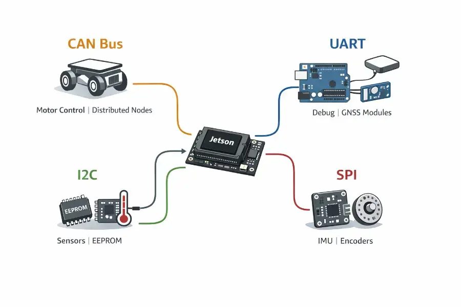
That distinction matters because modern robots rarely use only one protocol. A Jetson-based robot can expose UART, SPI, I2C, and CAN on the same platform; high-performance IMUs commonly support SPI and I2C; motor controllers often expose UART and CAN; and industrial Arduino-class control hardware can mix CAN, UART, SPI, and I2C in the same system. In other words, advanced robots are usually multi-bus systems by design, not by accident.
The practical answer is usually this:
Use CAN for distributed actuators, wheel drives, battery systems, and anything that must survive noisy cabling across the robot body.
Use SPI for the fastest local sensors such as IMUs, encoders, ADCs, and flash, especially when latency matters.
Use I2C for simple board-level peripherals like EEPROMs, RTCs, temp sensors, GPIO expanders, and lower-rate housekeeping sensors.
Use UART for the simplest point-to-point links: debug console, GNSS, bootloader, or a straightforward Jetson-to-MCU bridge during prototyping.
These are all communication protocols, each with its own strengths and weaknesses for different robot subsystems.
Widely adopted communication protocols often benefit from better hardware and software support, making integration and troubleshooting easier.
That is the short answer. The real engineering answer is below.
The first principle: bus choice follows robot geometry
A robot has several communication zones.
Inside a single PCB, the priorities are usually low latency, low pin count, and easy driver support. Across a whole limb, chassis, or moving harness, the priorities change completely: EMI tolerance, cable length, connectors, termination, fault handling, and predictable behavior under stress start to dominate. That is why SPI can be perfect for an IMU mounted a few centimeters from an MCU, but a terrible choice for a wheel module half a meter away next to motor currents. Conversely, CAN may be excessive for a tiny EEPROM on the same board, but ideal for a distributed set of joint controllers. This division matches current Jetson I/O options, Bosch sensor guidance, CAN-based drive ecosystems, and Arduino industrial control hardware.
So before comparing nominal bandwidth, compare distance, topology, and noise environment.
CAN (controller area network): the robot-body network
CAN exists for exactly the class of problems that robotics creates: many nodes, short control messages, shared wiring, electrical noise, and the need to keep operating even when the environment is ugly. TI’s overview describes CAN as a multi-master, message-broadcast system with a maximum signaling rate of 1 Mbit/s for classic CAN, and Bosch’s original CAN specification emphasizes prioritization, multicast reception, multimaster operation, error detection, error signaling, automatic retransmission, and fault confinement. CAN stands for controller area network, as defined in the ISO 11898 standard, which specifies its physical and data link layer for robust vehicle and industrial communication.
That is why CAN feels so natural in robotics. Wheel modules, joint drives, battery packs, IO nodes, and safety-adjacent devices often need to share a bus and exchange relatively small but important messages: state, torque commands, velocity, temperatures, limits, fault codes, heartbeats, and enable/disable transitions. This is exactly the kind of traffic CAN was designed for. Higher-layer profiles such as CiA 402 standardize drive behavior for servo drives, stepper drives, and frequency inverters, and CiA also defines a service robot control profile family.
From a physical-layer perspective, classic high-speed CAN is happiest as a linear bus with 120 Ω termination at both ends, short stubs, and twisted pair. TI’s physical-layer note gives the common rule-of-thumb numbers engineers still use: about 40 m at 1 Mbit/s, 100 m at 500 kbit/s, 200 m at 250 kbit/s, and shorter stubs at higher rates; it also recommends keeping un-terminated stub length very short, around 0.3 m in the high-speed 1 Mbit/s case.
For robotics, that translates into a simple design rule: if the wire leaves the main compute box and runs through the robot near motors, start by assuming CAN.
CAN and CAN FD are both bus protocols that define how data is exchanged in automotive and industrial systems. CAN FD extends the idea by keeping classic arbitration behavior while allowing a faster data phase. Common controller implementations such as Microchip’s MCP2517FD/MCP2518FD family support 1 Mbit/s arbitration and up to 8 Mbit/s data rate, and current motor ecosystems like ODrive already expose CAN-based control with experimental CAN-FD support.
Within CAN communication, the data link layer (as defined by ISO 11898) is responsible for defining frame formats, error handling, and ensuring reliable data transfer, which is key to CAN’s robustness. CAN messages can be of several types: a data frame carries the actual data payload, a remote frame is used to request data from another node, and an overload frame signals that a node is busy and needs more time before processing further messages.
A CAN data frame consists of several fields, including the identifier, control bits, and the data field, which contains the actual data being transmitted between nodes. The data length field specifies how many bytes of actual data are included, determining the amount of information that can be sent in a single CAN message.
That does not mean CAN is perfect. It is not the right place for high-volume raw data streams, such as unprocessed sensor or camera data, large binary blobs, or camera traffic. It is a control network, not a video bus. And while it is robust, it also demands discipline: proper transceivers, termination, bitrate selection, cable quality, and bus topology matter a lot. For diagnostics and troubleshooting, capturing and analyzing bus data is essential for system monitoring and identifying issues.
When CAN is the right answer
Use it for:
motor control boards across a chassis
distributed joint controllers
battery management and power modules
safety-related state exchange
embedded motion devices speaking CANopen/CiA 402 or vendor CAN protocols
When CAN is the wrong answer
Avoid it for:
raw cameras
high-volume logging streams
very fast local sensor readout on the same PCB
simple one-device local links where UART or SPI is easier
UART: the simplest serial communication link in the room
UART is a bit different from the others in this article. Strictly speaking, it is less a shared network bus than a simple serial link mechanism. UART is a form of serial communication protocol, transmitting data one bit at a time over a single data line. Espressif’s documentation describes UART as the hardware feature that handles timing and data framing for asynchronous serial interfaces such as RS-232, RS-422, and RS-485, and notes that it can be used in full-duplex or half-duplex depending on the electrical layer around it. Arduino’s documentation presents it as one of the most common device-to-device serial protocols, with familiar baud rates such as 9600 and 115200 in everyday use.
This is why UART is everywhere in robotics.
It is the bus of bring-up, debug, and “just make the first prototype work.” Jetson debug consoles use UART. GNSS receivers often expose UART. Smart modules and modems frequently expose UART. Many motor controllers support UART. ODrive, for example, documents a default UART baudrate of 115200 and provides a dedicated Arduino UART guide for runtime control.
UART’s strength is not topology. Its strength is frictionless simplicity. Two devices, TX/RX, common ground in TTL-style setups, and you are moving data. The transmitter and receiver are the two endpoints responsible for sending and receiving data. No address map, no arbitration, no bus scanning, no termination math in the simple case.
But that simplicity is also the limitation. UART does not natively give you shared-bus arbitration, node addressing, or the kind of fault confinement CAN provides. If you outgrow “one device talks to one device,” you start inventing the missing layers yourself. That is often fine for one custom link between a Jetson and an MCU. It is usually a bad foundation for a whole distributed robot.
When using UART, the transmitting UART initiates communication by pulling the uart data transmission line (or data line) low to signal the start bit, changing the voltage level from high (idle) to low. The data transmission line is used for serial data transfer, and when idle, it remains at a high voltage level. The transmitting UART receives data in parallel from the data bus, frames it with start, parity, and stop bits, and then sends it serially to the receiving UART, which converts it back to parallel form. During data flow, devices send data, transfer data, and transmit data over UART; data is transferred serially from one device to another through the data line.
Cable length is where people get confused. UART framing is not the same thing as the physical layer. Raw 3.3 V TTL UART is usually for short, local runs. If you need longer or more robust links, you typically put RS-232, RS-422, or RS-485 transceivers behind the UART peripheral. TI’s RS-485 application data shows tests over 50 m, 100 m, 150 m, 200 m, and even 1000 m scenarios depending on data rate and transceiver family, which illustrates the core point: longer distance comes from the physical layer choice, not from “UART” alone.
For error detection, UART can use a parity bit, and communication is checked to ensure the parity bit matches the expected number of ‘1’ bits in the data frame, helping to detect transmission errors.
When UART is the right answer
Use it for:
debug and boot console
Jetson-to-one-MCU prototyping
GNSS, cellular, or simple smart peripherals
one motor board in the same enclosure
service/configuration ports
When UART is the wrong answer
Avoid it as the main distributed bus for:
many actuators across the robot
electrically noisy long harnesses without RS-485/RS-422 help
networks that need arbitration and deterministic priority behavior
I2C: the convenience bus for local peripherals
I2C is still one of the most useful protocols in embedded robotics because it solves a very common board-level problem elegantly: many simple peripherals, very few wires.
NXP’s specification defines I2C as a two-wire bus using SDA and SCL, with devices addressed in software, true multi-controller arbitration, collision detection, and speeds up to 100 kbit/s in Standard-mode, 400 kbit/s in Fast-mode, 1 Mbit/s in Fast-mode Plus, and 3.4 Mbit/s in High-speed mode. It also makes the electrical model very clear: I2C uses open-drain/open-collector style signaling with pull-ups, and the number of devices is constrained by bus capacitance.
That electrical detail is the entire story.
I2C is fantastic when the devices are local: EEPROM, RTC, temperature sensor, power monitor, small IMU, magnetometer, GPIO expander, fan controller, or configuration peripheral on the same board or in the same enclosure. It is not naturally a “run this all through a legged robot harness next to motors” protocol. NXP’s documentation repeatedly comes back to capacitance limits, with the specification centered around a 400 pF bus load envelope unless you add repeaters, buffers, switches, or extenders. NXP also documents that special buffering solutions can stretch I2C much farther, even into tens of meters, but that is an engineered extension of I2C, not the default assumption.
This is why I2C is so common on sensor breakout boards and so often disappointing when people try to treat it like a body bus.
In robotics, I2C is best thought of as the housekeeping and low/medium-rate peripheral bus. It minimizes pin count and cabling inside a local subsystem. It is especially attractive when the data rate is moderate and the sensors are not latency-critical. Arduino’s Wire library support and Jetson’s exposed I2C lines make it easy to integrate.
When I2C is the right answer
Use it for:
EEPROM / FRAM
RTCs
temperature / voltage / current sensors
GPIO expanders
lower-rate local sensors
board management and configuration peripherals
When I2C is the wrong answer
Avoid it as your default for:
long moving cables through the robot
high-rate latency-sensitive IMU pipelines
distributed motor control
electrically harsh actuator environments
SPI: the performance bus with clock signal for local devices
SPI is usually the fastest and most direct answer when a sensor or peripheral sits close to the processor and you care about latency. Linux kernel documentation describes SPI as a simple and efficient synchronous interface with clock, MOSI, and MISO, commonly in the 1–20 MHz range in Linux systems, and an additional chip-select line per peripheral. The clock signal is essential in SPI, as it synchronizes data transfer between the master and slave devices, ensuring that both sides are aligned during communication. It is also explicitly described as full duplex. Importantly, the same documentation notes that SPI is a de facto interface rather than a tightly unified standard, which is why details vary between devices.
That is exactly why SPI is so good for robotics sensors.
SPI has no bus arbitration and no addressing in the I2C sense. That sounds like a weakness, but locally it is often a strength. The host owns the clock, transactions are direct, overhead is low, and throughput can be high. If you want fast register access to an IMU, high-rate encoder data, quick ADC samples, or flash storage, SPI is usually the first protocol to check. Bosch explicitly recommends SPI for latency-critical multisensory applications on BMI08x devices, with a recommended SPI clock above 2 MHz for fastest sensor readout.
There is also a useful systems insight here: even CAN can arrive through SPI. Microchip’s external CAN FD controllers are themselves SPI-attached peripherals, which is a common pattern when a host processor does not expose the desired CAN interface directly or when you want a separate dedicated controller.
SPI’s weakness is physical scale. Once you leave the local board and start running through long harnesses or across joints, its benefits evaporate quickly. Separate chip selects, shared clock integrity, ground reference quality, and skew become the problem. SPI is brilliant on a PCB and increasingly painful the farther it travels.
When SPI is the right answer
Use it for:
IMUs
magnetic encoders
ADCs / DACs
flash / FRAM
FPGA or coprocessor local links
external CAN controllers like MCP2518FD
When SPI is the wrong answer
Avoid it for:
multi-node robot-body wiring
long cables through joints and limbs
“just keep adding devices” topologies where chip-select fanout becomes awkward
Error detection and correction in robotics communication
In robotics, reliable data transmission is non-negotiable—especially when electronic control units (ECUs), sensors, and actuators must coordinate seamlessly in real time. Error detection and correction mechanisms are at the heart of ensuring that every data frame sent across a communication bus arrives intact, even in the presence of electrical noise, interference, or physical faults.
Each communication protocol—UART, SPI, and CAN—approaches error detection differently, reflecting their intended use cases and physical layer realities.
UART is a classic example of serial data transmission where error detection is typically handled by adding a parity bit to each data frame. This parity bit allows the receiving device to check if the number of data bits set to ‘1’ matches the expected parity (even or odd). If a mismatch is detected, the receiving UART can request a retransmission, helping to maintain data integrity. For more robust applications, especially over longer distances or in noisy environments, higher layer protocols may add cyclic redundancy checks (CRC) or implement acknowledgment and retransmission schemes to further reduce the risk of corrupted data.
SPI offers high-speed, synchronous data transfers, but basic SPI mode does not include built-in error detection at the protocol level. Instead, error detection and correction are usually implemented in higher layer protocols or within the application logic. For example, when transferring critical sensor data or image data, engineers may add CRCs or checksums to the data payload, ensuring that the receiving device can verify the integrity of the data bytes received. In embedded systems where SPI is used for local, high-speed links, the physical proximity and controlled environment often reduce the risk of transmission errors, but robust applications still benefit from software-level error detection.
CAN protocol stands out for its comprehensive, hardware-level error detection and correction features, making it a preferred communication bus for distributed robotics systems. Every CAN frame includes a CRC field calculated from the data bytes, as well as additional error detection mechanisms such as bit stuffing, frame checks, and acknowledgment slots. If a receiving device detects a CRC mismatch or other error, it can signal an error frame on the bus, prompting retransmission of the affected data packet. This built-in fault tolerance is a key reason why CAN is trusted for mission-critical data transfers between actuators, battery systems, and safety modules. CAN FD (Flexible Data Rate) further enhances these capabilities by supporting larger data payloads and higher data rates, while maintaining robust error detection.
In complex robotics systems, higher layer protocols often add another layer of reliability. Techniques such as data repetition, forward error correction, and acknowledgment packets ensure that even if a data transmission is corrupted, the system can recover gracefully. For example, a host computer might send a write command multiple times or require explicit acknowledgment from the target device before proceeding to the next data frame. These strategies are especially important in environments with high electromagnetic interference or when long distance data transfers are required.
When selecting a communication bus for your robot, consider not just the maximum data rate or physical layer characteristics, but also the protocol’s ability to detect and correct errors. A good communication bus for robotics should offer robust error detection, support flexible data rates, and integrate easily with your embedded computer and other devices. While CAN protocol is often the default for distributed, fault-tolerant systems, newer standards like CAN FD provide even greater reliability and throughput for demanding applications.
Ultimately, ensuring data integrity across your robot’s communication bus options is essential for safe, predictable, and efficient operation. By understanding the strengths and limitations of each protocol’s error detection and correction features, robotics engineers can design systems that keep data flowing reliably—even in the most challenging environments.
Jetson + Arduino + distributed robot: what should you actually do?
Here is the architecture I would recommend for a serious hobby or professional prototype robot.
A Jetson should usually run perception, planning, VLM/LLM logic, mapping, UI, and high-level ROS 2 orchestration. NVIDIA’s current documentation shows Jetson Orin Nano developer hardware exposing I2C, SPI, and UART on the 40-pin header with 3.3 V signal levels, and Jetson Linux also documents CAN support on Orin Nano/NX platforms, with an external CAN transceiver required.
An Arduino-class MCU or industrial control MCU should usually own the tight loops: PWM generation, encoder capture, local safety interlocks, sensor timestamping, watchdog behavior, and motor control state machines. In the Arduino ecosystem, boards and carriers now exist with serious field connectivity; for example, the GIGA R1 exposes a dedicated CAN bus but requires an external transceiver, while Portenta Machine Control includes an onboard CAN transceiver and also exposes RS-232/RS-422/RS-485 plus I2C.
Between the Jetson and the MCU, choose based on physical distance and system maturity:
UART if the Jetson and MCU sit in the same enclosure and you want the fastest path to a working prototype.
CAN if the MCU becomes a real distributed controller on the robot body, or if you want the architecture to survive scale, noise, and multiple nodes.
Inside each control PCB:
put the IMU and fast encoders on SPI
put EEPROM, RTC, power monitors, and expanders on I2C
keep a UART service/debug port because you will eventually need it
Across the robot body:
use CAN or CAN FD for wheel modules, joint boards, and distributed actuator nodes
ensure you use the same connector type for all CAN bus connections to maintain compatibility and reliable data recording across multiple CAN networks
That stack scales well because each bus is solving the problem it was built for.
What advanced robotics and embedded systems are doing now
Two state-of-the-art trends are worth knowing.
The first is that CAN is still very relevant in robotics, especially with CANopen and CAN FD. CiA continues to maintain motion and robotics-related profiles, including CiA 402 for drives and a service-robot control profile family. That is a strong sign that CAN remains a real embedded robotics network, not just legacy automotive baggage. In modern communication protocols like CAN, the order of bits within data frames—such as the least significant bit (LSB) and most significant bit (MSB)—plays a crucial role in how data is encoded and transmitted, ensuring compatibility and reliable data exchange between devices.
The second is that some local sensor designs are slowly outgrowing classic I2C. MIPI I3C is explicitly positioned as an evolutionary successor that improves on I2C while keeping backward compatibility, and current MIPI/NXP material highlights speeds up to 12.5 MHz, dynamic addressing, and in-band interrupts. That matters mostly for local sensor fabrics, not for robot-body actuation networks.
And once you move into high-end industrial or tightly synchronized multi-axis machines, the comparison often shifts beyond all four buses in this article toward EtherCAT, which the EtherCAT Technology Group explicitly describes as widely used in robotics, including motion and safe-motion use cases.
So the modern picture is not “CAN lost to SPI” or “I2C lost to UART.” It is more like this:
SPI wins the fast local sensor lane.
I2C wins the convenient local peripheral lane.
UART wins the simplest direct-link lane.
CAN wins the distributed embedded control lane.
EtherCAT / industrial Ethernet enters when the machine becomes larger and more synchronized.
I3C is the main technology to watch on the local sensor side.
Final verdict
If you want one sentence to remember, make it this:
SPI for speed, I2C for convenience, UART for simplicity, CAN for robot wiring.
Or said another way:
If the device is fast and close, prefer SPI.
If the device is simple and close, prefer I2C.
If the link is one-to-one and easy, prefer UART.
If the node is farther away, noisy, or one of many actuators, prefer CAN.
The biggest mistake in robotics is not choosing the “wrong famous protocol.” It is choosing a protocol that does not match the distance, topology, and failure mode of the subsystem you are building.
And that is why the best robots do not pick one bus.
They pick the right bus, zone by zone.