Sensor fusion drift is rarely caused by “the filter being bad.”
In real robots, drift usually comes from a broken contract somewhere around time, frames, calibration, covariance, motion assumptions, or sensor trust. The EKF, UKF, factor graph, or localization stack is often just the first place where the lie becomes visible.
That is why debugging drift by randomly tuning noise values is a trap. It can make a short demo look better while hiding the physical fault that will return on a longer run, a different floor, a faster turn, or a warmer IMU.
The better question is:
Which physical assumption did the estimator believe that the robot violated?
This guide is the field workflow I would use before touching filter parameters. It builds on the sensor model in what sensor fusion means in robotics, the TF and camera geometry notes in ROS 2 camera calibration, TF2, and optical frames, and the evidence stack from ROS 2 logs and rosbags for robot debugging.
Key takeaways
- Sensor fusion drift is usually a system problem: wrong timestamps, frame ownership, calibration, covariance, synchronization, wheel slip, IMU bias, or stale transforms.
- Start by separating three failures: the robot moved differently than the model assumed, the sensors measured the world incorrectly, or the estimator trusted the wrong signal at the wrong time.
- Do not tune covariance until you have verified TF frames, sensor timestamps, static transforms, topic rates, unit conventions, and repeatable rosbag evidence.
- Debug drift with controlled motion tests: stationary, straight line, square path, in-place rotation, acceleration/braking, and known loop closure.
- A good drift investigation produces a minimal bag, a TF tree snapshot, a timing table, residual plots, and a written hypothesis before parameter changes.
- For AI-assisted debugging, the useful artifact is not a chat transcript. It is a structured failure record that ties observed drift to sensor evidence and estimator assumptions.
Citation-ready answer
To debug sensor fusion drift in a real robot, first verify the contracts that the estimator depends on: coordinate frames, timestamps, static transforms, sensor calibration, covariance, topic rates, and motion assumptions. Then replay controlled rosbag tests to isolate whether drift appears while stationary, during straight motion, during rotation, after acceleration, or after sensor dropout. Only tune filter noise after proving that the input data is time-aligned, expressed in the correct frames, physically plausible, and consistent with the robot’s operating mode.
Drift is a symptom, not a root cause
When a robot’s estimated pose slowly separates from reality, it is tempting to blame the localization stack.
Sometimes the filter is configured badly. But most real failures are upstream:
| Symptom | Common root cause | First check |
|---|---|---|
| Robot drifts while stationary | IMU bias, encoder noise, nonzero velocity input, bad covariance | Stationary bag with all motion commands zero |
| Robot curves during straight motion | Wheel radius mismatch, encoder sign error, axle width error, wheel slip | Straight-line tape test and odometry delta |
| Heading diverges during turns | Gyro bias, wrong IMU frame, yaw covariance too low, bad angular velocity units | In-place rotation bag and TF orientation check |
| Pose jumps after visual update | Camera extrinsic error, wrong optical frame, stale transform, visual covariance too confident | Camera/TF timestamp and calibration replay |
| Map pose is stable but odom drifts | Normal local odometry drift | REP-105 frame interpretation |
| Odom and map both drift | Bad local odometry, bad global correction, or wrong fusion policy | Split local and global estimator outputs |
| Drift gets worse after acceleration | IMU saturation, wheel slip, time offset, acceleration model mismatch | Acceleration/braking test |
| Drift appears only after minutes | Thermal IMU bias, clock drift, memory/CPU pressure, long-term wheel slip | Long stationary and long loop bag |
The pattern is important: drift is not one bug. It is a family of failures that look similar on a map.
First, protect the frame contract
Before looking at EKF parameters, inspect the frame model.
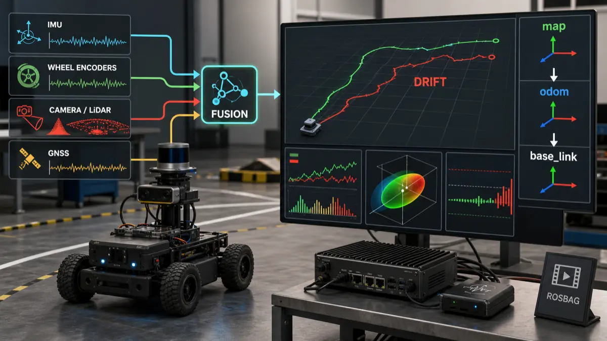
ROS has a standard way to reason about mobile robot frames. REP-105 defines common coordinate frames such as map, odom, and base_link, and the distinction matters:
mapis globally consistent but can jump when global corrections arrive.odomis locally continuous but can drift over time.base_linkis the robot body frame.
That means odom drift is not automatically a bug. An odometry frame is allowed to drift. What is not acceptable is mixing frame responsibilities until nobody knows which transform owns continuity, global correction, or robot body geometry.
A clean mental model is:
1 | map |
If your stack fuses global measurements directly into the wrong estimator, publishes two competing transforms, or treats map and odom as interchangeable, drift debugging becomes guesswork.
The official ROS 2 tf2 documentation is worth reading with this exact question in mind: which node owns each transform, and at what time?
The drift triage order
Use this order before touching noise values:
- Confirm the robot is physically healthy: tires, drivetrain, encoders, mount rigidity, sensor brackets, cable strain, IMU placement.
- Confirm the TF tree: one owner per transform, correct parent/child direction, correct static transforms, no duplicate publishers.
- Confirm timestamps: sensor headers, transform timestamps, clock source, bag playback time, driver latency.
- Confirm units and signs: meters, radians, rad/s, m/s, ENU/NED assumptions, encoder direction, IMU axes.
- Confirm calibration: camera intrinsics, camera-to-base extrinsics, IMU orientation, LiDAR mount, wheel radius, wheelbase.
- Confirm covariance: realistic uncertainty, not zero, not copied blindly, not overconfident on weak sensors.
- Confirm estimator mode: which variables are fused, which frame is output, whether differential or absolute updates are intended.
- Confirm observability: logs, bags, topic rates, residuals, diagnostics, transform latency.
- Only then tune filter parameters.
If you skip steps 1-8, parameter tuning becomes a way to bury evidence.
Capture the right bag
A useful drift bag is small, controlled, and annotated.
Do not start with a 40-minute chaotic run through a lab. Start with six short tests:
| Test | Duration | What it isolates |
|---|---|---|
| Stationary warmup | 2-5 min | IMU bias, encoder noise, false velocity, thermal drift |
| Straight line | 5-10 m | wheel scale, encoder signs, yaw leakage, slip |
| Square path | 4 turns | yaw drift, axle width, turn model, loop closure error |
| In-place rotation | 360 degrees each way | gyro sign, yaw units, IMU frame, angular covariance |
| Accel/brake | several repeats | time offset, wheel slip, IMU saturation, drivetrain lag |
| Sensor dropout | controlled disable/re-enable | fallback behavior, covariance, estimator recovery |
For each bag, record the same minimum evidence:
1 | /tf |
The exact topic names differ, but the principle does not: record the estimator input, the estimator output, the command that caused motion, and the transforms that explain frame ownership.
The ROS 2 rosbag2 package documentation at docs.ros.org is the right starting point for building repeatable capture and replay workflows.
The timing table
Timestamps are one of the fastest ways to create fake drift.
Build a table like this from the bag:
| Stream | Rate | Header age | Jitter | Frame | Notes |
|---|---|---|---|---|---|
| IMU | 100 Hz | 6 ms | 2 ms | imu_link | stable |
| Wheel odom | 50 Hz | 18 ms | 5 ms | odom to base_link | delayed under CPU load |
| Camera odom | 15 Hz | 95 ms | 40 ms | camera_optical_frame | bursty |
| GNSS | 5 Hz | 120 ms | 30 ms | gnss_link | absolute, noisy near building |
| TF static | once | n/a | n/a | sensor frames | verify extrinsics |
| Estimator output | 50 Hz | 12 ms | 4 ms | odom to base_link | output continuous |
Two red flags show up quickly:
- a slow sensor is being treated as fresh,
- a high-confidence sensor arrives late and pulls the estimate toward old reality.
This connects directly to real-time Linux for robotics. You do not need hard real-time for every perception process, but you do need to understand latency, jitter, CPU pressure, and stale state when estimator outputs influence robot behavior.
Covariance is not decoration
Covariance tells the estimator how much to trust a measurement.
Bad covariance creates two opposite failures:
| Covariance mistake | Result |
|---|---|
| Too confident | Weak or delayed sensor dominates the estimate |
| Too uncertain | Useful sensor is ignored |
| Zero covariance | Filter may treat uncertain data as perfect |
| Same covariance in all modes | Robot ignores speed, surface, lighting, GPS quality, or sensor health |
| Copied example values | Parameters look clean but do not describe the machine |
This is especially dangerous when mixing wheel odometry, IMU, visual odometry, LiDAR odometry, and GNSS. Each sensor fails differently:
- wheel encoders are precise until slip,
- IMUs are responsive but biased,
- cameras can fail under blur, low texture, lighting changes, or wrong calibration,
- LiDAR can fail in sparse or repetitive geometry,
- GNSS can jump, lag, or degrade near buildings.
The ROS robot_localization package documentation at docs.ros.org is useful because it forces you to think in terms of state variables, frames, covariance, and sensor update behavior rather than just “fuse everything.”
Calibration failures that look like drift
Calibration bugs often masquerade as estimator bugs.
| Calibration issue | Typical drift pattern |
|---|---|
| Wrong IMU mounting orientation | yaw or roll/pitch coupling during turns |
| Camera optical frame wrong | visual odometry jumps or rotates unexpectedly |
| Camera-to-base extrinsic wrong | pose update is locally consistent but globally offset |
| Wheel radius mismatch | straight motion slowly curves |
| Wrong wheelbase | in-place rotations over-turn or under-turn |
| LiDAR angle offset | scan matching works in one direction but drifts in turns |
| GNSS antenna offset ignored | heading or pose shifts during rotation |
| Loose sensor mount | drift changes after vibration or impact |
The practical rule:
If drift appears under one motion primitive, suspect geometry before tuning the filter.
For camera/IMU systems, calibration is its own discipline. Tools such as Kalibr exist because camera intrinsics, camera-to-IMU extrinsics, time offset, and motion excitation all matter. You do not need Kalibr for every robot, but you do need the same seriousness about sensor geometry.
A failure-mode decision matrix
Use this matrix during investigation:
| Observation | Likely class | Next experiment |
|---|---|---|
| Estimate moves while robot is physically still | bias/noise/trust | stationary warmup, inspect velocity inputs |
| Straight-line command creates arc | drivetrain geometry/slip | tape line test, compare left/right encoder deltas |
| Rotation angle is wrong both directions | wheelbase/gyro scale | in-place rotation with external reference |
| Rotation error changes by direction | wheel asymmetry/backlash | clockwise vs counterclockwise bags |
| Visual odometry jumps when robot turns | extrinsics/optical frame/time offset | camera TF audit and camera-only replay |
| GNSS correction causes sudden pose jump | global/local frame policy | inspect map/odom ownership and covariance |
| Drift appears under CPU load | latency/jitter/dropout | compare topic age and scheduler load |
| Drift starts after 10 minutes | thermal bias or accumulated slip | long stationary and long loop closure bag |
| Estimator improves when a sensor is removed | sensor covariance or calibration | isolate that sensor with replay |
| Filter output is smooth but wrong | over-trusted model | compare raw measurements to ground truth |
The point is to turn a vague complaint into a falsifiable hypothesis.
Debugging workflow
Here is the practical loop:
- State the failure in one sentence: “After a 10 m straight run, the estimate is 0.4 m left of the tape line.”
- Capture one controlled bag that reproduces it.
- Draw the TF tree and mark the owner of every transform.
- Make a timing table from the bag.
- Plot raw sensor deltas before estimator output.
- Compare motion command, wheel odometry, IMU yaw, visual odometry, and fused output.
- Disable one sensor in replay, not on the live robot first.
- Change one parameter or calibration value at a time.
- Re-run the same bag.
- Write the conclusion before moving to the next hypothesis.
This is slow in the same way good debugging is slow. It prevents you from spending three days tuning values that were compensating for a reversed frame.
Where AI-assisted debugging can help
An LLM can help summarize bags, logs, parameter files, and failure records. It should not guess the fix from a vague symptom.
Good AI-assisted tasks:
- summarize which topics were recorded,
- compare expected and observed topic rates,
- flag stale transforms,
- list duplicate TF publishers,
- extract estimator parameters,
- generate a hypothesis table,
- compare before/after test results,
- draft a regression checklist.
Bad AI-assisted tasks:
- “tune my EKF until it works”,
- “guess the covariance values”,
- “ignore the frame warning”,
- “make the robot trust the camera more because the plot looks noisy.”
This is the same boundary I use for evaluating a local LLM for robotics tool use. Let AI organize evidence and propose checks. Keep physical authority and estimator changes inside a repeatable validation loop.
The acceptance checklist
Before declaring the drift fixed, require all of this:
- stationary bag shows no meaningful pose creep,
- straight-line test matches the physical line within the required tolerance,
- square path returns close to the start pose,
- in-place rotation matches external heading reference,
- TF tree has one owner per dynamic transform,
- static transforms are measured and documented,
- sensor timestamps are within the allowed freshness budget,
- covariance values are justified by measurements or datasheets,
- replaying the same bag before and after the fix shows improvement,
- the fix survives a different speed, surface, and lighting condition,
- logs explain what changed and why.
For safety-relevant robots, drift should also feed degraded-mode decisions. If localization confidence drops, motion authority should shrink before the robot becomes dangerous. That is the same design pressure behind robot safety architecture.
FAQ
Is odom drift always a problem?
No. In the REP-105 model, odom is locally continuous and can drift over time. The problem is uncontrolled drift, wrong frame ownership, or treating a drifting local estimate as globally correct.
Should I tune EKF covariance first?
No. Verify frames, timestamps, calibration, units, topic rates, and physical drivetrain behavior first. Covariance tuning should describe measured uncertainty, not hide broken inputs.
Why does drift get worse during turns?
Turns expose IMU frame errors, gyro bias, wheelbase mistakes, wheel slip, angular velocity unit errors, and camera/LiDAR extrinsic problems. Use in-place rotation tests in both directions before changing estimator gains.
What bag should I record first?
Record a short stationary bag and a straight-line bag. They isolate false motion, timestamp issues, encoder scale, yaw leakage, and basic TF errors faster than a complex mission bag.
Can visual odometry fix bad wheel odometry?
Sometimes, but it can also hide the drivetrain bug until lighting, texture, blur, or CPU load changes. Fix the physical odometry model before relying on visual correction.
What is the most common hidden cause?
Bad time alignment is one of the most common hidden causes. A delayed but overconfident sensor can pull the estimate toward a physically old state and look like drift, especially during acceleration and turns.
Final thought
Sensor fusion drift is not a tuning puzzle. It is a contract audit.
Your estimator believes a story about time, frames, sensor geometry, motion, uncertainty, and trust.
When the robot drifts, find the part of the story that stopped matching the machine.