
For a robot to intelligently interact with its environment, “seeing” is not enough. It needs to understand where objects are in its physical space. This seemingly simple act of perception is, in fact, one of the most complex challenges in robotics, requiring a precise synergy between camera hardware, software calibration, and a robust spatial representation framework.
The Robot Operating System (ROS) is an open-source robotics middleware suite originally developed by Willow Garage, a pioneering institution in robotics between 2007 and 2013. Willow Garage played a foundational role in the robotics community, contributing innovations such as the PR2 robot and fostering open-source initiatives that shaped the current robotics landscape.
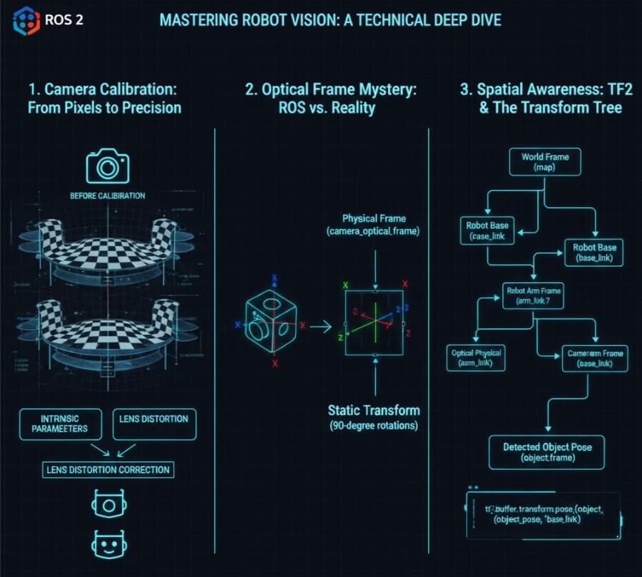
In the world of ROS 2 (Robot Operating System 2), achieving true spatial awareness from camera feeds involves mastering three critical concepts: Camera Calibration, understanding the perplexing Optical Frame, and leveraging the power of TF2 for coordinate transformations. ROS features a package management system that organizes code into reusable packages, similar to Linux distributions, and benefits from strong community support with a vast ecosystem of software, tutorials, and contributors. ROS technology is widely used in applications such as autonomous mobile robots (AMRs), drones, and manufacturing systems. Over successive generations, ROS has evolved from its early versions to ROS 2, expanding its capabilities and impact on robotics technology and research. This article will provide a comprehensive, technical deep dive into these essential elements, guiding you from raw pixels to actionable 3D insights.
1. Why Your Robot is Blind Without Calibration: The World of Intrinsic Parameters
Imagine a human with blurry vision, or one who perceives straight lines as curves. They can “see,” but their understanding of reality is distorted. A raw camera, fresh out of the box, is essentially in this state. Its lens introduces distortions, and its internal geometry is unknown to the robot. For a robot, understanding its environment means knowing the precise relationship between a 2D pixel in an image and a 3D ray in space. This is where Camera Calibration comes in, determining the camera’s intrinsic parameters. Camera calibration is crucial for applications ranging from smartphone photography to self-driving cars, as it ensures accurate perception and measurement in computer vision systems.
Camera calibration relies on a mathematical equation that relates 3D world points to 2D image points. The process is used to determine camera parameters, including both intrinsic and extrinsic parameters, which are essential for mapping the real world to the camera’s image. To achieve high accuracy, it is necessary to calibrate the camera by performing camera calibration, which involves calculating intrinsic and extrinsic parameters using images of a known calibration pattern. This allows you to calculate accurate camera parameters, which are essential for correcting lens distortion, measuring object sizes, and determining the camera’s location in a scene.
The Role of the Checkerboard: Your Robot’s Eye Chart
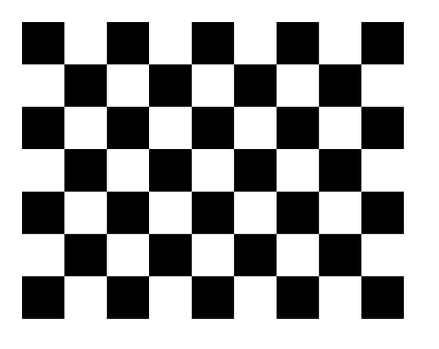
To fix this “blurry vision,” we use a precisely manufactured checkerboard as a calibration pattern (or ChArUco board for more robustness). This isn’t just a fancy pattern; it’s a known geometric reference object used to establish correspondences between object points in real world space (the 3D coordinates of the checkerboard corners, typically with Z=0) and image points (the 2D coordinates in the captured image). When the camera captures calibration images of this checkerboard from various angles—ideally using multiple images to improve accuracy and robustness, often stored in jpg format—the calibration software (like ROS 2’s camera_calibration package) can perform complex calculations.
The process involves:
Detecting Corners: Identifying the precise pixel coordinates of the checkerboard’s internal corners in each calibration image.
Known Geometry: Knowing the exact physical size of each square on the checkerboard and defining the object points in real world space.
Solving for Intrinsics: Using algorithms (e.g., Zhang’s method) to solve a system of equations that model the camera’s internal characteristics, using multiple calibration images for robust results.
After calibration, reprojection errors are calculated by comparing the projected object points to the detected image points to evaluate the accuracy of the calibration. Typically, two radial distortion coefficients are sufficient for most lenses, but three may be needed for severe distortion. It’s important to experiment with different calibration techniques and settings to achieve the best results.
Radial distortion causes straight lines to appear curved, especially near the edges of an image, while tangential distortion occurs when the lens and the image plane are not parallel, affecting image accuracy. Correcting these distortions is essential for accurate 3D reconstruction in applications like virtual reality and augmented reality.
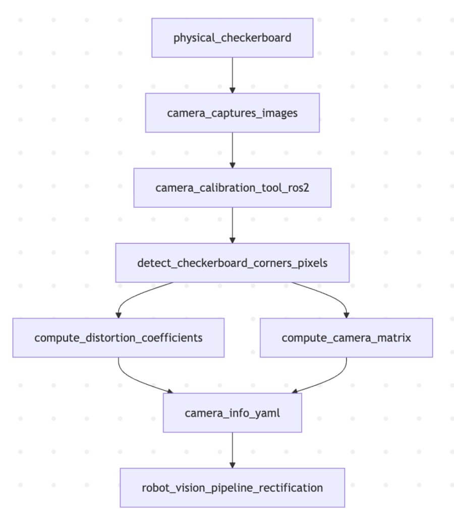
Schematic: The Camera Calibration Process**This diagram illustrates how a physical checkerboard is used with a camera calibration tool to compute intrinsic parameters, stored in a YAML file, which are then used for image rectification.
The primary outputs stored in a camera_info.yaml file are:
Distortion Coefficients (k1, k2, p1, p2, k3): These numbers describe how the lens distorts the image (radial and tangential distortion). They allow the software to rectify the image, making straight lines appear straight again.
Camera Matrix (fx, fy, cx, cy): This 3x3 matrix (also known as the intrinsic matrix or K matrix) describes the internal geometry of the camera:
(fx, fy): Focal lengths in pixels along the X and Y axes.
(cx, cy): The coordinates of the principal point (optical center) in pixels.
Technical Implication: With these intrinsic parameters, your robot can now perform undistortion (rectification) on every incoming image and accurately project a 2D pixel coordinate back into a 3D ray in the camera’s frame of reference. Without this, any distance or position measurement based on visual input would be fundamentally flawed.
2. The Optical Frame Mystery: ROS Standard vs. Optical Standard
This is where many beginners stumble. You’ve calibrated your camera, and the image looks correct. Yet, when you try to measure distances or orient objects, everything seems rotated or flipped. This is due to the crucial distinction between the physical camera_link frame and the convention-driven camera_optical_frame in ROS 2. Knowing the camera’s location in the 3D scene is essential for accurate image analysis and object measurement, as it allows you to align the scene with real-world coordinates.
Physical camera_link (Body Frame)
Definition: This frame represents the physical mounting of the camera. Its origin is typically at the center of the camera lens or its mounting point.
Axes: In ROS, all physical links and frames (like your robot’s base_link or a gripper_link) follow a common convention:
X-axis: Points forward.
Y-axis: Points left.
Z-axis: Points up. This makes sense for a robot’s body.
Logical camera_optical_frame (Sensor/Image Frame)
Definition: This frame is a convention used to align with the typical image coordinate system and optical principles. It’s a virtual frame, not directly corresponding to a physical part of the camera’s housing.
Axes: This frame’s axes are defined as follows:
X-axis: Points right on the image plane.
Y-axis: Points down on the image plane.
Z-axis: Points forward along the optical axis (the direction the camera is looking).
The Discrepancy: A 90-Degree Rotation
The key difference is the Z-axis: In camera_link, Z points up. In camera_optical_frame, Z points out through the lens. This means the camera_optical_frame is typically a rotation of camera_link. Often, camera_optical_frame is obtained by rotating camera_link by -90 degrees around the Y-axis, then -90 degrees around the (new) X-axis.
Why this matters:
Image Processing: Computer vision algorithms (OpenCV, etc.) typically expect the image coordinate system to have X right, Y down. The camera_optical_frame aligns perfectly with this.
3D Point Clouds: When you generate 3D point clouds from a depth camera, these points are naturally expressed in the camera_optical_frame because its Z-axis aligns with the depth perception.
ROS Standard Compliance: Downstream ROS nodes often expect visual data (like point clouds or recognized object poses) to be published in camera_optical_frame by convention.
To bridge this gap, a static transformation is published between camera_link and camera_optical_frame. This tells the ROS 2 TF2 system how to convert coordinates between the camera’s physical mounting and its optical perception.
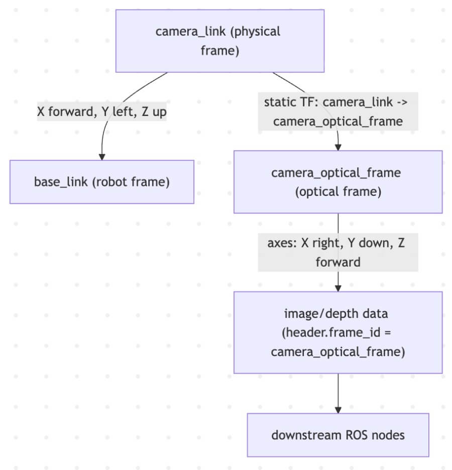
Schematic: Bridging camera_link and camera_optical_frame This diagram highlights the different axis conventions and how a static transform connects the physical and optical frames.
Undistortion and Re-projection Error: Making Pixels Tell the Truth
When it comes to robot vision, capturing an image is just the beginning. To ensure your robot can accurately interpret its environment, you must correct for the inevitable lens distortion and rigorously evaluate the quality of your camera calibration. This is where the concepts of undistortion and re-projection error come into play—turning raw, distorted pixels into reliable data for robotics and computer vision applications.
3. Spatial Awareness: Linking Camera Vision to the Robot’s Body with TF2
Once the camera is calibrated (intrinsics known) and its optical frame understood, the final piece of the puzzle is to situate the camera within the robot’s overall kinematic chain. This is the realm of Extrinsic Calibration and TF2 (Transform Tree).
In the robot operating system (ROS), processes are represented as nodes in a graph structure, connected by edges called topics. This architecture enables peer to peer communication and flexible interfaces between components, allowing seamless data exchange and command execution. ROS provides a comprehensive range of services, including hardware abstraction, low-level device control, and support for multi-robot systems, making it suitable for diverse robotics applications.
Although ROS is not a real-time operating system, it can be integrated with real-time computing code. ROS 2, a major revision of the ROS API, adds support for real-time and embedded systems, and by 2026 is recognized as the industry-standard middleware for robotics development, suitable for industrial and mission-critical applications.
The ROS ecosystem offers a rich collection of software libraries, packages, and ROS packages, which allow users to implement and control various functionalities such as hardware drivers, algorithms, and sensor interfaces. These are organized using a package management system, facilitating modular development and rapid prototyping. Tools like RViz for visualization and Gazebo for simulation, along with other utilities for data visualization, recording, and automation, are integral to the ROS workflow.
Comprehensive documentation, tutorials, and community-driven support are available for users, providing details on different ROS versions, packages, and technical procedures. The modular architecture of ROS allows users to implement, swap, and control components as needed, supporting flexible system integration from development to production.
Extrinsic Calibration: Where is the Camera on the Robot?
Extrinsic calibration determines the rigid transformation (translation and rotation) between the camera’s physical frame (camera_link) and a known reference frame on the robot, typically base_link or a specific joint. This answers the question: “If the camera is here, where is it relative to the robot’s main body?”
This can be done:
Manually: By carefully measuring the mounting position (less precise).
Algorithmically: By using a known target (like the checkerboard again) that is also visible to the robot’s base frame (e.g., mounted on the floor), or by hand-eye calibration if the camera is on a robotic arm.
This transformation is then typically added to the robot’s URDF (Unified Robot Description Format) file as a fixed joint or published as a static transform.
The Power of TF2: The Coordinate Frame Dictionary
TF2 is the cornerstone of coordinate transformations in ROS 2. It maintains a tree of all known coordinate frames and allows any node to ask: “What is the pose of object X (in camera_optical_frame) relative to base_link (of the robot) at this exact time?” TF2 will then compute the chain of transformations automatically.
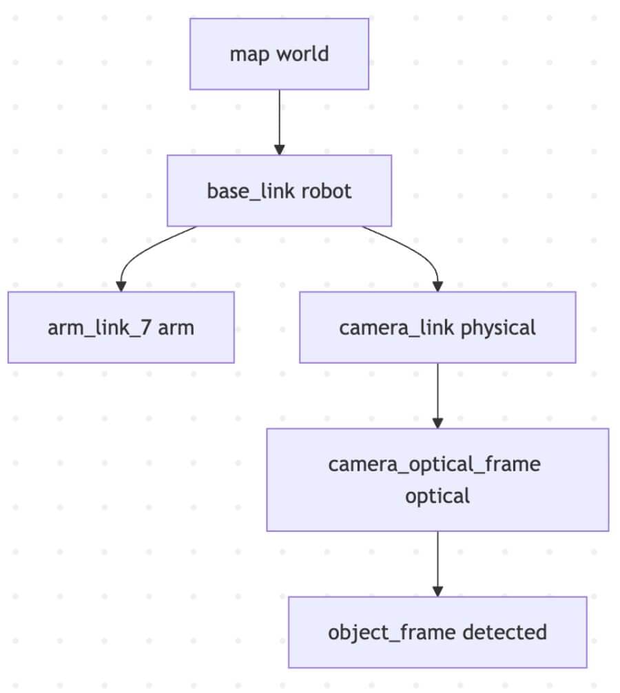
Schematic: A Simplified TF2 Tree Example This illustrates how TF2 manages hierarchical transformations, allowing objects detected by the camera to be localized relative to the robot’s base or the world map.
Practical Example with TF2 Lookups:
Imagine your camera detects a ball at (x, y, z) in its camera_optical_frame. For a robotic arm to pick it up, it needs the ball’s position relative to its own gripper, or to the robot’s base.
Object Detection Node:
Subscribes to /camera/image_rect (rectified images).
Processes the image, detects a ball, and determines its 3D pose in camera_optical_frame.
Publishes a geometry_msgs/msg/PoseStamped message for the ball, with its header.frame_id set to camera_optical_frame.
Manipulation Node:
Receives the ball’s pose message.
Uses tf2_ros.Buffer and transform_pose() to request: “Transform this ball’s pose from camera_optical_frame to base_link.”
TF2 traverses the tree (camera_optical_frame -> camera_link -> base_link) and returns the ball’s pose in the robot’s base frame.
Now the arm knows exactly where to move to grasp the ball.
Python
1 | # Pseudo-code for a TF2 lookup in Python (ROS 2) |
Pseudo-code: Using TF2 to transform a detected object’s pose.
Conclusion: From Pixels to Precision
Mastering camera vision in ROS 2 is a journey from understanding lens imperfections to navigating complex coordinate systems. By diligently calibrating your cameras (intrinsic parameters), understanding the conventions of the camera_optical_frame (and its relation to the physical camera_link), and expertly utilizing the TF2 framework (for extrinsic parameters and runtime transformations), you equip your robot with true spatial awareness.
No longer is your robot merely processing pixels; it is perceiving objects in a 3D world, understanding their relationships to its own body, and preparing to interact with them with precision. This deep integration of visual input with the robot’s physical kinematics is a fundamental pillar of intelligent robotics and Cyber-Physical Systems, unlocking capabilities from autonomous navigation to dexterous manipulation.