
A beginner-friendly “memory dump” with every command explained, end-to-end, reboot-persistent (JetPack 6 / Orin family)
This is the write-up I wish I had the first time: every step, every command, and why we do it. It’s designed so that:
Future me can reproduce it months later without re-learning everything on JetPack 6.x
Beginners can follow safely without bricking their boot config
Setting up GPIO output on Nvidia Jetson Orin Nano Super is not easy at first. Here is how I manage to succeed and understand how I will be autonomously able to configure the PINs as I want.
Big credit to JetsonHacks for making Device Tree Overlays understandable and practical. Their article on overlays is the mental model that “unblocked” us.
Jetson Orin Nano/ Nano Super Header Pins mapping
Why GPIO feels “hard” on Jetson Orin Nano Super
If you are coming from Arduino, Raspberry Pi, or even classic embedded Linux boards, configuring a GPIO pin on Nvidia Jetson Orin Nano Super can feel unnecessarily complex — even hostile.
You plug a LED, type a command, and… nothing happens.
Or worse: the board no longer boots after a reboot.
This is not because you are doing something wrong.
It is because Jetson boards are fundamentally different machines.
The Jetson Orin Nano Super is not a hobbyist SBC designed around GPIO-first usage. It is:
a high-performance AI edge computer
designed primarily for CUDA, vision, robotics, and inference
built on a server-class SoC (Tegra 234)
shipped with a production-grade Linux boot pipeline
GPIO exists — but it is not the primary abstraction.
This article explains why GPIO configuration is difficult on Jetson, and then shows how to do it correctly, safely, and permanently.
The goal is not just to “make a LED blink”, but to understand:
how pins are actually wired internally
why changes must happen at boot time
why Device Tree Overlays are required
how to avoid breaking your system
If you understand this once, you will never be blocked again.
Big credit goes to JetsonHacks, whose work and explanations on Device Tree Overlays finally made this mental model click. Their article “Device Tree Overlays on Jetson: Scary but fun!” is the conceptual foundation behind everything shown here.
Why GPIO is complicated on Jetson Orin (the missing explanation)
This is the section that most tutorials skip — and the one that causes the most confusion.
1) Jetson pins are NOT “GPIO by default”
On many boards (Arduino, Raspberry Pi):
a pin is a GPIO
software merely toggles it
On Jetson Orin, a physical header pin is only a wire connected to the SoC.
What that wire does depends on hardware multiplexing.
That pin may be connected internally to:
UART
I2C
SPI
PWM
I2S
GPIO
or multiple options, but only one at a time
The selection is done by a hardware pin multiplexer (pinmux).
👉 If the pinmux says “UART”, Linux GPIO tools will not work — no matter what command you type.
2) Pinmux is configured BEFORE Linux starts
This is the second major trap.
The pinmux is not a runtime Linux setting.
It is configured:
during early boot
by the bootloader
based on the Device Tree
That means:
You cannot fix it with a Python script
You cannot fix it with a shell command
You must reboot to apply changes
This is why:
“It worked until reboot”
is almost always a pinmux / overlay problem.
3) The Device Tree is a hardware contract, not a config file
Think of the Device Tree as:
“A formal contract between the hardware and the kernel”
It answers questions like:
Which pins exist?
What are they connected to?
What drivers should claim them?
What electrical mode should they use?
Changing GPIO configuration means changing that contract.
Replacing the whole Device Tree (.dtb) works — but is dangerous.
Device Tree Overlays exist to solve this exact problem:
modify only what you need
without copying or forking Nvidia’s base DT
safely and incrementally
This is why JetsonHacks insists so much on overlays — and why they are the correct solution.
4) Header pin numbers ≠ GPIO numbers
Another major source of confusion.
On Jetson:
“Pin 7” is not a GPIO number
“Pin 11” is not a GPIO number
They are connector positions.
The real identifiers are:
SoC pin names (e.g.
uart1_rts_pr4)GPIO controller + line number (e.g.
gpiochip0 line 112)
The mapping chain is:
HDR40 pin → SoC signal → pinmux → GPIO controller → line number
If you skip one link in that chain, nothing works.
5) Jetson is designed for production, not tinkering
This is not a criticism — it’s a design choice.
Nvidia optimized Jetson for:
deterministic boot
stable hardware descriptions
reproducible deployments
robotics and industrial use
That means:
GPIO changes are explicit
configuration is static
mistakes are not silently ignored
This is why the system feels strict — and why it is reliable once understood.
Why JetsonHacks is essential here
JetsonHacks bridges the gap between:
Nvidia’s low-level documentation
and what makers / roboticists actually need
They provide:
working examples
safe workflows
correct mental models
Most importantly, they explain why overlays are scary but necessary, instead of pretending GPIO is simple when it isn’t.
This article builds directly on that foundation.
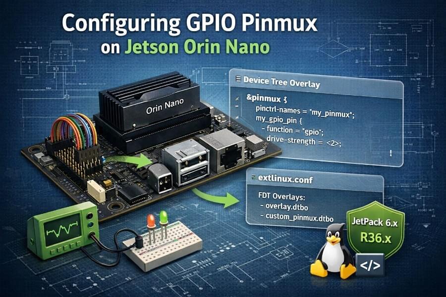
0) What you’re actually doing (the “why” before the “how”)
On Jetson Orin (including Orin Nano Super), each physical header pin can be routed to different internal functions (GPIO, I2C, SPI, PWM, etc.) via a hardware multiplexer called the pinmux.
Linux users often assume GPIO is “just software,” but on Jetson:
The kernel needs a hardware description at boot time telling it which SoC signals are GPIO.
That description comes from the Device Tree (DTB).
The clean way to customize DTB without replacing it is a Device Tree Overlay (DTBO).
So the goal is:
Create a DT overlay that says:
“The SoC signals connected to header pin 7 and header pin 11 must be configured as GPIO outputs at boot.”
JetsonHacks explains this “map of the hardware” idea well, including why overlays are safer than editing the base tree.
Also, first and foremost, before going deeper into this article, first follow JetsonHacks tutorial to get started and get your PIN 7 working. Here is the github repo link and video tutorial to proceed:
https://github.com/jetsonhacks/jetson-orin-gpio-patch
1) Prerequisites and safety checks
1.1 Identify your JetPack / L4T version (important context)
Why: NVIDIA sometimes changes boot/DT handling between releases. If something behaves differently, version matters.
cat /etc/nv_tegra_release
You’ll see something like an L4T release line. Keep it in your notes.
1.2 Install required tools
We need the Device Tree Compiler (dtc) to compile .dts → .dtbo.
sudo apt update
sudo apt install -y device-tree-compiler
Verify the tool exists:
dtc --version
Why: Overlays must be compiled correctly, and we’ll use -@ to include symbol data (commonly required for overlays).
1.3 Install GPIO user tools (optional but very helpful)
Why: gpioinfo, gpioset, etc. make debugging straightforward.
sudo apt install -y gpiod
2) Back up your boot configuration (do this, seriously)
On Jetson Linux, the boot menu is commonly controlled by:
/boot/extlinux/extlinux.conf
Why backup: a typo in extlinux.conf can prevent normal boot.
sudo cp -a /boot/extlinux/extlinux.conf /boot/extlinux/extlinux.conf.bak
Confirm:
ls -l /boot/extlinux/
If something goes wrong later, you can restore it (from recovery or by mounting the SD/NVMe elsewhere).
NVIDIA documents that extlinux.conf is used to point to DTB settings.
3) Understand what we’re changing: pinmux in the device tree
We are going to write an overlay that targets the pinmux node (commonly something like /pinmux@2430000 on Orin).
Why: that node is where pin function (GPIO vs other) gets configured at boot.
JetsonHacks specifically calls out that header pins may be part of the pinmux/bus hierarchy and that you can inspect /proc/device-tree on a running system.
4) Create the overlay source file (.dts)
4.1 Create a working directory
Why: keep your overlay sources organized and reproducible.
mkdir -p ~/jetson-gpio-overlay
cd ~/jetson-gpio-overlay
4.2 Create the overlay DTS (FULL FILE)
Create gpio-pins-7-11.dts:
nano gpio-pins-7-11.dts
Paste the entire file below, this is the one I use on my Jetson Orin Nano Super:
/dts-v1/;
/plugin/;

/ {
    jetson-header-name = "Jetson 40pin Header";
    overlay-name = "Pin 7 + Pin 11 gpio bidirectional";
    compatible =
        "nvidia,p3768-0000+p3767-0000\0"
        "nvidia,p3768-0000+p3767-0001\0"
        "nvidia,p3768-0000+p3767-0003\0"
        "nvidia,p3768-0000+p3767-0004\0"
        "nvidia,p3768-0000+p3767-0005\0"
        "nvidia,p3768-0000+p3767-0000-super\0"
        "nvidia,p3768-0000+p3767-0001-super\0"
        "nvidia,p3768-0000+p3767-0003-super\0"
        "nvidia,p3768-0000+p3767-0004-super\0"
        "nvidia,p3768-0000+p3767-0005-super\0"
        "nvidia,p3509-0000+p3767-0000\0"
        "nvidia,p3509-0000+p3767-0001\0"
        "nvidia,p3509-0000+p3767-0003\0"
        "nvidia,p3509-0000+p3767-0004\0"
        "nvidia,p3509-0000+p3767-0005";

    fragment@0 {
        target = <&pinmux>;

        __overlay__ {
            pinctrl-names = "default";
            pinctrl-0 = <&jetson_io_pinmux>;

            jetson_io_pinmux: exp-header-pinmux {
                hdr40-pin7 {
                    nvidia,pins = "soc_gpio59_pac6";
                    nvidia,tristate = <0x0>;
                    nvidia,enable-input = <0x1>;
                    nvidia,pull = <0x0>;
                };

                hdr40-pin11 {
                    nvidia,pins = "uart1_rts_pr4";
                    nvidia,tristate = <0x0>;
                    nvidia,enable-input = <0x1>;
                    nvidia,pull = <0x0>;
                };
            };
        };
    };
};
What each key line means (beginner explanation)
/dts-v1/;
Declares the device tree source format version./plugin/;
Declares this file is an overlay (not a full base DT).compatible = "nvidia,p3768-0000+p3767-0005-super", ...This overlay does not target the SoC directly (
tegra234).Instead, it targets specific Jetson board combinations:
- the Orin Nano module (
p3767) - mounted on the Orin Nano Super / Dev Kit carrier board (
p3768) - including the
-supervariants used by JetPack 6+
This is the same approach used by JetsonHacks and jetson-io generated overlays.
Why this matters:
the overlay is only applied if the board actually matches
it prevents accidental application on incompatible Jetson models
it is safer than a generic SoC-wide match
fragment@0 { target = <&pinmux>; ... }
This tells the overlay to apply its changes to the existing pinmux node.
&pinmuxis a symbol exported by the base Device Tree, which points to the
SoC pin multiplexer configuration node (typically located at/pinmux@2430000on Orin systems).Why this approach is preferred:
- it avoids hard-coding absolute paths
- it is resilient to DT layout changes between JetPack versions
- it matches how JetsonHacks and NVIDIA-generated overlays work
This is also why the overlay must be compiled with
dtc -@,
so symbol references like&pinmuxare preserved.- the Orin Nano module (
nvidia,pins = "soc_gpio59_pac6";
The internal SoC signal name we are configuring.nvidia,tristate = <0>;
Forces the pin to be actively driven (not floating).nvidia,enable-input = <1>;This keeps the input buffer enabled, even though the pin is used as GPIO.
Important clarification:
- this does not force the pin to be an input
- GPIO direction (input vs output) is selected later by user-space
viagpioset,libgpiod, or Python
Keeping input enabled allows:
- bidirectional GPIO usage
- read-back of the pin state
- safer debugging and testing
Output driving is controlled when the GPIO line is requested
withLINE_REQ_DIR_OUT.
This overlay configures the pinmux only.
It does not force the pin direction; direction is selected at runtime
by the GPIO consumer (gpioset, gpiod, Python, etc.).
Note: the exact
nvidia,pinsstring is the most common place people get stuck. If your pin names differ, you must adapt them (see the “How to add more pins” section later).
5) Compile overlay source (.dts) into binary (.dtbo)
Run:
dtc -@ -I dts -O dtb -o gpio-pins-7-11.dtbo gpio-pins-7-11.dts
Why these flags?
-I dts: input is device tree source-O dtb: output is compiled binary format (used by bootloader/kernel)-o ...: output filename-@: include symbol information used by overlay mechanisms (common requirement).
Verify the file exists:
ls -lh gpio-pins-7-11.dtbo
6) Install the overlay in a standard location
A common place used on Jetson is:
/boot/
Note: On Jetson Linux, extlinux.conf accepts absolute paths for overlays.
Placing the .dtbo directly in /boot/ is valid and works reliably.
Other layouts (such as /boot/dtb/overlays/) are also possible,
but this article sticks to the simplest proven configuration.
Copy your overlay:
sudo cp -a gpio-pins-7-11.dtbo /boot/
Confirm:
ls -lh /boot/
7) Enable the overlay at boot via extlinux.conf
This is the step that makes the change persistent across reboot.
7.1 Open the config
sudo nano /boot/extlinux/extlinux.conf
7.2 Full working example extlinux.conf (template)
Here is the complete modified file from JetsonHacks that works for me for PIN 7 and 11:
⚠️ Important: you MUST replace <YOUR_APP_PARTUUID> with the value
from your own device. Copying this value from another system will
prevent your Jetson from booting.
⚠️ The DTB filename below is specific to JetPack 6.x on Orin Nano Super.
Always verify the correct filename on your system:
ls /boot/dtb/
Use the DTB that matches your board, then update the FDT line accordingly.
FDT /boot/dtb/<YOUR_DTB>.dtb

TIMEOUT 30
DEFAULT JetsonIO

MENU TITLE L4T boot options

LABEL primary
      MENU LABEL primary kernel
      LINUX /boot/Image
      INITRD /boot/initrd
      APPEND ${cbootargs} \
             root=PARTUUID=<YOUR_APP_PARTUUID> \
             rw rootwait rootfstype=ext4 \
             mminit_loglevel=4 \
             console=ttyTCU0,115200 \
             firmware_class.path=/etc/firmware \
             fbcon=map:0 \
             video=efifb:off \
             console=tty0 \
             nv-auto-config

LABEL JetsonIO
      MENU LABEL Custom Header Config: <HDR40 Pin 7 gpio bidirectional>
      LINUX /boot/Image
      FDT /boot/dtb/kernel_tegra234-p3768-0000+p3767-0005-nv-super.dtb
      INITRD /boot/initrd
      APPEND ${cbootargs} \
             root=PARTUUID=<YOUR_APP_PARTUUID> \
             rw rootwait rootfstype=ext4 \
             mminit_loglevel=4 \
             console=ttyTCU0,115200 \
             firmware_class.path=/etc/firmware \
             fbcon=map:0 \
             video=efifb:off \
             console=tty0 \
             nv-auto-config
      OVERLAYS /boot/gpio-pins-7-11.dtbo
To find your PARTUUID (update the file above with yours):
sudo blkid | grep 'PARTLABEL="APP"'
Save and exit.
8) Reboot (this is when pinmux actually changes)
sudo reboot
Why: pinmux is applied at boot. Changing overlay files without reboot usually won’t reconfigure the hardware.
9) Verify the overlay actually applied
9.1 Inspect device tree live view
Dump the live tree:
sudo dtc -I fs -O dts -o /tmp/running.dts /proc/device-tree
Why: /proc/device-tree is the “truth” of what the kernel sees right now.
Now search for your overlay node names:
grep -n "hdr40-pin7" /tmp/running.dts
grep -n "hdr40-pin11" /tmp/running.dts
grep -n "exp-header-pinmux" /tmp/running.dts
sudo cat /sys/firmware/devicetree/base/bus@0/pinmux@2430000/exp-header-pinmux/hdr40-pin11/nvidia,pins | tr -d '\0'
If you see them, the overlay applied.
If you don’t see them:
overlay didn’t load
the target path is wrong
or
OVERLAYSline wasn’t parsed
(That’s why the backup step matters.)
10) Find the GPIO line numbers and test output (using gpiod)
10.1 List GPIO chips and lines
gpioinfo
Why: Jetson exposes GPIO controllers as gpiochipX and each “pin” becomes a line number inside a chip.
You’re looking for line names that match the SoC pin or header mapping.
10.2 Quickly toggle a line (example)
Once you identify the right gpiochipN and line L, do:
sudo gpioset gpiochipN L=1
Turn off:
sudo gpioset gpiochipN L=0
Why sudo? Many systems restrict GPIO control to root unless you set udev rules.
Tip: If you’re driving an LED, always use a resistor (e.g., 220Ω–1kΩ), otherwise you can damage the pin or LED.
PIN 7 mapping
Header : HDR40 pin 7
SoC pin :
SOC_GPIO59_PAC6GPIO line : 144
Chip :
gpiochip0gpiofind “PAC.06”
→ gpiochip0 144
Test to put the GPIO pin to HIGH then LOW from your command line:
sudo gpioset gpiochip0 144=1

sudo gpioset gpiochip0 144=0
PIN 11 mapping
From tegra234-p3767-0000-common-hdr40.dtsi :
Header : HDR40 pin 11
SoC pin :
UART1_RTS_PR4GPIO name :
PR.04GPIO line : 112
Chip :
gpiochip0sudo gpioinfo gpiochip0 | grep PR.04
→ line 112: “PR.04”
Test to put the GPIO pin to HIGH then LOW from your command line:
sudo gpioset gpiochip0 112=1
sudo gpioset gpiochip0 112=0
11) Python test (simple and explicit)
Install python bindings if needed:
python3 -c "import gpiod; print(gpiod.__version__)"
If that fails, install:
sudo apt install -y python3-gpiod
Minimal test script test_pin.py:
import time import gpiod

CHIP = "gpiochip0"  # change me
LINE = 112 # change me
chip = gpiod.Chip(CHIP)
line = chip.get_line(LINE)

line.request(consumer="pin-test", type=gpiod.LINE_REQ_DIR_OUT)
for _ in  range(5):
    line.set_value(1)
    time.sleep(0.5)
    line.set_value(0)
    time.sleep(0.5)

line.release()
Run:
python3 test_pin.py
12) How to add more GPIO output pins (after 7 and 11)
This is the scalable part: you don’t “repeat the whole tutorial,” you only add more pin blocks.
12.1 Step A — Identify the SoC pin name for that header pin
This depends on the carrier board mapping.
Practical ways:
Use JetsonHacks guidance and inspect
/proc/device-treefor pinmux entries and existing pin names.Use
jetson-io.py(when available) to see header functions and generate overlays (nice for beginners; still uses DT under the hood).Use community mappings / reference overlays (but verify against your JetPack version).
12.2 Step B — Add a new node in the overlay
Example for an additional pin name soc_gpioX_yyZ:
some_other_pin_gpio_output {
    nvidia,pins = "soc_gpioX_yyZ";
    nvidia,pull = <0>;
    nvidia,tristate = <0>;
    nvidia,enable-input = <0x1>;
};
We keep input enabled to allow bidirectional / readback; output is controlled by gpioset request direction.
12.3 Step C — Recompile, copy, reboot
Same commands as before:
dtc -@ -I dts -O dtb -o gpio-pins-7-11.dtbo gpio-pins-7-11.dts
sudo  cp -a gpio-pins-7-11.dtbo /boot/
sudo reboot
13) Alternatives to “raw GPIO” (when you want to go further)
GPIO is fine for:
LEDs
buttons
simple enable pins
But robotics/CPS often needs:
precise timing
safe motor control
deterministic behavior
Common alternatives:
PWM (for servos / dimming / speed control)
I2C/SPI expanders (MCP23017, etc.) to get more I/O cleanly
A dedicated microcontroller (Arduino / STM32 / RP2040) handling real-time I/O
Jetson does “brains”
MCU does “reflexes”
This architecture is extremely common in robotics because Linux is not hard real-time.
14) Troubleshooting checklist (the real-world gotchas)
If it worked before reboot but not after
That usually means you were using a temporary user-space approach or the overlay wasn’t loaded at boot. Re-check:
OVERLAYSline exists and has correct pathoverlay file exists in
/boot/dump
/proc/device-treeandgrepfor your overlay nodes
If gpioinfo shows the line but output doesn’t change
pin might still be muxed to another function
or there is a hardware conflict (another driver grabbing it)
If device tree dump doesn’t contain your nodes
overlay didn’t apply
wrong
target-pathcompilation missing
-@
Conclusion (expanded, long-term perspective)
What you actually learned (even if it felt painful)
If you followed this article end to end, you didn’t just enable GPIO pins.
You learned:
how Jetson boots
how hardware is described to Linux
how pinmux works
how to safely modify low-level hardware configuration
how to debug GPIO properly
This knowledge transfers directly to:
PWM
SPI
I2C
camera interfaces
audio
custom carrier boards
robotics deployments
Why this pain is worth it
Once configured correctly:
GPIO works reliably
survives reboots
behaves predictably
integrates cleanly with Python, C++, ROS, or systemd
This is exactly what you want in:
autonomous machines
long-running edge deployments
A final architectural recommendation
If you find yourself needing:
many GPIOs
strict timing
fast interrupts
motor control
safety guarantees
Do not fight Linux.
Use this architecture:
Jetson Orin = brain (AI, vision, planning) Microcontroller = reflexes (GPIO, motors, timing)
This is not a workaround — it is industry standard.
Final words
GPIO on Jetson Orin Nano Super is difficult by design, not by accident.
Once you accept that:
hardware description comes first
Linux is not in charge of pinmux
overlays are the correct tool
Everything becomes consistent.
Scary? Yes.
Fun? Eventually.
Powerful? Absolutely.
And once you’ve done it once — you’ll never be blocked again.
References (worth reading)
JetsonHacks: “Device Tree Overlays on Jetson: Scary but fun!”
NVIDIA docs mention editing
extlinux.conffor DTB and overlay conceptsNVIDIA forum discussion on best practices for DT modifications (overlays are generally preferred)
Expanded context: GPIO output pins in robotics, technical details, and real-world applications
The Jetson Orin Nano Super Developer Kit includes essential hardware such as a power cable and supports storage expansion via a compatible SD card, which is important for embedded and robotics projects. Keeping your system updated with the latest software and performing a software upgrade—or even just a software upgrade—can unlock new features and generative AI capabilities.
In robotics, GPIO output pins are used to control various devices and components, and robots utilize GPIO output pins to interface with actuators and sensors. GPIO output pins can be programmed to send signals to control motors, lights, and other devices in robotic systems. In robotics, GPIO output pins are essential for enabling communication between the microcontroller and external components, and robotics applications often involve the integration of GPIO output pins for effective control and automation.
Technically, GPIO pins can drive relays using low-power output signals to switch high-power AC or DC devices. Current limits for most GPIO pins typically range from 16mA to 40mA. PWM capabilities for LED dimming and motor speed control are not supported by all GPIO pins. GPIO pins typically provide low voltage (3.3V or 5V) and very limited current (often < 20 mA). Using resistors can help limit current when driving components like LEDs. Many GPIO pins support hardware-level communication protocols like I2C, SPI, or UART. Ensuring the voltage compatibility between a board’s logic level and peripheral components is important to avoid damage, as applying a voltage higher than a GPIO pin’s rating can permanently damage the hardware. LED control involves toggling LEDs on and off or using PWM to dim them. Some GPIO pins have permanent internal pull-up resistors and may toggle randomly during the boot process. Standard GPIO pins typically source/sink small amounts of current (around 8mA), while High-Drive pins can handle up to 40mA.
The ability of GPIO output pins to provide flexible control and automation is critical in robotic systems. They can be programmed to perform specific tasks, such as controlling actuators or reading sensor data, which is fundamental in robotics engineering and the integration of mechanical components. These capabilities are widely used in manufacturing, logistics, and other industrial fields, where efficiency, automation, and reliability are essential.
The Jetson Orin Nano Super Developer Kit is used in engineering education, robotics, manufacturing, and logistics, supporting the design and control of mechanical components and systems. In human-robot interaction, robots are designed to work alongside humans, understand human behaviors, and sense their environment using GPIO-connected sensors. Platforms like NVIDIA Metropolis leverage AI and vision to improve efficiency and safety in industries such as retail, smart cities, and healthcare.
Finally, the Jetson Orin Nano Super improves efficiency in robotic systems and industrial applications, making it a key tool for advancing automation and AI at the edge.
Hardware Requirements
The NVIDIA Jetson Orin Nano Super Developer Kit sets a new standard for accessible, high-performance AI and robotics development. Whether you’re building humanoid robots, collaborative robots, or mobile robots, understanding the hardware requirements is essential for unlocking the full potential of this powerful platform.
At the core, the developer kit requires a stable power supply ranging from 9V to 19V DC, ensuring that the board and all its components receive reliable electrical power for consistent, high performance operation. The kit conveniently includes a 19V power adapter and a selection of power cables, such as a Type B cable for US, JP, CA, and PH, and a Type I cable for CN, so you can get started right out of the box, no matter your region.
From a mechanical perspective, the Jetson Orin Nano Super Developer Kit is engineered for flexibility and expansion. The board features a rich array of IOs, including multiple USB 3.2 Gen 2 ports for high-speed data transfer, dual M.2 Key M slots for SSD storage, and a pre-installed Wi-Fi module for seamless connectivity. The 40-pin expansion header and 12-pin control/UART header provide complete control over GPIO pins, making it easy to interface with a wide range of sensors, actuators, and other hardware. A dedicated 4-pin fan connector ensures your system stays cool, even under demanding AI workloads.
Storage and memory are equally robust. With 8GB of LPDDR5 memory delivering a bandwidth of 102 GB/s, the kit is well-equipped for high performance inference and real-time AI processing. The microSD slot supports UHS-1 cards up to SDR104 mode, and the dual M.2 slots allow for substantial storage expansion—ideal for projects involving large language models, generative AI models, or vision language models.
The Jetson Orin Nano Super Developer Kit is more than just hardware; it’s your gateway to a broad AI software ecosystem. NVIDIA’s comprehensive suite of tools and libraries empowers you to create, deploy, and optimize AI applications across a wide range of domains. Whether you’re experimenting with generative AI, vision AI, or deploying advanced vision transformers, the kit’s powerful GPU and Ampere architecture deliver the performance boost needed for next generation AI workloads.
For students, researchers, and engineers, the developer kit offers invaluable hands-on experience in computer science, control systems, and mechanical construction. Its accessible platform is perfect for STEM education, enabling learners to explore the intersection of robotics, artificial intelligence, and embedded systems. The board’s GPIO pins, UART, and I2C interfaces provide the building blocks for integrating sensors, actuators, and custom hardware, opening up new possibilities for innovative robotic systems and autonomous machines.
In summary, the NVIDIA Jetson Orin Nano Super Developer Kit combines robust hardware, a wide range of IOs, and seamless integration with a broad AI software ecosystem. It’s the ideal platform for anyone looking to push the boundaries of robotics, AI, and embedded technology—whether you’re developing industrial robots, social robots, or exploring the future of human robot interaction. With the right tools, power supply, and a passion for technology, you’re ready to create the next generation of intelligent machines.