If you build robots with ROS 2 long enough, you eventually hit the same architectural question:
You have sensors. You have motors. You have a PID controller, maybe an MPC controller, maybe a trajectory planner. You also have hardware drivers, simulation, URDF files, and ROS 2 nodes publishing commands.
But one question remains:
What is the clean layer that connects controllers to real hardware without turning the robot into a pile of custom code?
That layer is ros2_control.
In my opinion, this is one of the most important missing pieces between “I can run ROS 2 nodes” and “I can build a real robot control stack”. I already covered topics like PID vs MPC in robotics, Real-Time Linux for robotics, ROS 2 architecture patterns, and micro-ROS between a Jetson and a real-time microcontroller. The natural next step is the framework that actually sits between controllers and hardware.
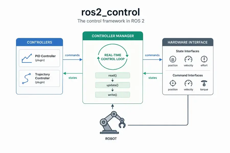
The official documentation describes ros2_control as a framework for real-time robot control in ROS 2. Its Controller Manager is the central component that manages controller lifecycle, access to hardware interfaces, and services exposed to the ROS world.
Sources used for this article:
- ros2_control official documentation
- Controller Manager documentation
- Writing a new hardware component
- ROS 2 Control documentation on docs.ros.org
TL;DR
ros2_control is the standard ROS 2 framework for connecting robot controllers to hardware through explicit interfaces.
The important idea is simple:
1 | ROS 2 commands |
The Controller Manager runs the control loop, manages the lifecycle of controllers, and coordinates access to hardware interfaces. Hardware interfaces expose what the robot can measure and command: position, velocity, effort, GPIO, sensors, or custom interfaces.
Real-time control with ros2_control is not automatic. The framework is designed for real-time-friendly execution, but deterministic behavior still depends on your Linux kernel, thread scheduling, memory allocations, logging, hardware bus, and driver implementation.
What is ros2_control?
ros2_control is a control framework for ROS 2 that separates three things that should not be mixed:
- the controller logic,
- the hardware-specific driver logic,
- the orchestration layer that connects both safely.
A controller should not need to know whether a motor command is sent over CAN, UART, EtherCAT, USB, SPI, or a custom microcontroller bridge. It should only know that a joint exposes a state interface and accepts a command interface.
This separation is what makes ros2_control so useful.
Instead of writing one custom control stack per robot, you describe what the robot exposes, load controllers as plugins, and let the Controller Manager coordinate the control loop.
A simple mental model is:
1 | Controller = control law |
Why ros2_control exists
Without a framework like ros2_control, many robotics projects naturally drift toward this pattern:
1 | ROS topic callback |
This may work for a prototype.
But it becomes painful when you need:
- multiple controllers,
- clean controller switching,
- simulation and hardware parity,
- reusable control code,
- predictable timing,
- hardware abstraction,
- lifecycle management,
- and integration with tools like MoveIt, Nav2, or Gazebo.
ros2_control exists to make that layer explicit.
It gives you a standardized way to say:
Here is my robot hardware. Here are its state interfaces. Here are its command interfaces. Here are the controllers allowed to use them.
That is much cleaner than hiding everything inside arbitrary ROS 2 nodes.
The core architecture
At the highest level, ros2_control looks like this:
1 | High-level ROS 2 nodes |
The most important pieces are:
- Controller Manager: loads, configures, activates, deactivates, updates, and switches controllers.
- Controllers: plugins that read state interfaces and write command interfaces.
- Hardware Components: plugins that expose robot hardware to the framework.
- Resource Manager: manages access to hardware resources and interfaces.
- URDF / ros2_control description: declares the hardware, joints, state interfaces, and command interfaces.
This is the part many beginners miss: in ros2_control, the controller does not directly talk to your motor driver. It talks to interfaces. The hardware component implements those interfaces.
Controller Manager explained simply
The Controller Manager is the central runtime component of ros2_control.
Its job is to keep the control system coherent.
It does three major things:
- manages controller lifecycle,
- runs the update loop,
- coordinates access to hardware interfaces.
The official documentation states that the Controller Manager is the main component in the framework and that it manages controller lifecycle, access to hardware interfaces, and services to the ROS world.
In practical terms, it is the process that answers questions like:
- Which controllers are loaded?
- Which controllers are configured?
- Which controllers are active?
- Which interfaces does each controller claim?
- Is it safe to switch from one controller to another?
- When should hardware be read and written?
- At what rate should the controller update loop run?
The ros2_control loop
The classic ros2_control loop is easy to remember:
1 | read(); |
Conceptually:
read()gets the latest state from the hardware.update()lets active controllers compute new commands.write()sends the commands back to the hardware.
For example, on a wheeled robot:
1 | read() |
On a robotic arm:
1 | read() |
This loop is where the real-time discussion begins.
Controller lifecycle
A controller in ros2_control is not just “running” or “not running”.
It has lifecycle states.
The typical states are:
1 | unconfigured -> inactive -> active |
This matters because robots are physical systems. You do not want a controller to start writing commands to hardware before it has been configured properly.
A simplified lifecycle looks like this:
1 | load controller |
This is especially important when switching control modes.
For example:
- joint state broadcaster active all the time,
- trajectory controller active during planned motion,
- effort controller active during torque experiments,
- emergency or hold controller active during fault states.
Lifecycle management is not administrative overhead. It is part of making robot behavior predictable.
Hardware interfaces explained simply
A hardware interface is the contract between your robot and ros2_control.
It tells the framework:
- what the robot can measure,
- what the robot can command,
- how those values are read,
- how those commands are written.
A joint may expose state interfaces such as:
1 | state_interfaces: |
And command interfaces such as:
1 | command_interfaces: |
This means:
- the hardware can report position, velocity, and effort,
- the controller is allowed to command position or velocity.
The controller does not know how those values are transported physically. That is the job of the hardware component.
State interfaces vs command interfaces
This distinction is essential.
A state interface is something the robot reports.
Examples:
- joint position,
- joint velocity,
- joint effort,
- sensor temperature,
- battery voltage,
- encoder ticks converted into radians.
A command interface is something the controller writes.
Examples:
- target position,
- target velocity,
- target torque,
- PWM duty cycle,
- gripper open/close command.
A controller reads state and writes commands.
1 | state interfaces -> controller -> command interfaces |
This is a small abstraction, but it changes the architecture completely.
Hardware component types
In ros2_control, hardware components are implemented as plugins. The official hardware component guide explains that hardware system components are libraries dynamically loaded by the Controller Manager using pluginlib.
The common hardware component categories are:
- System: a multi-joint or multi-device hardware system, such as a full robot arm or mobile base.
- Actuator: a single actuator, often representing one motor or one controllable unit.
- Sensor: a read-only component exposing state-like data.
For example, a differential drive base could be modeled as a system because both wheels are controlled through the same embedded board or motor controller.
A single smart servo could be modeled as an actuator.
An IMU, force sensor, or temperature board could be modeled as a sensor.
The design decision depends less on the physical shape and more on how communication and control are structured.
Example: a mobile base with ros2_control
Imagine a two-wheel differential drive robot.
The physical hardware includes:
- left motor,
- right motor,
- left encoder,
- right encoder,
- motor driver board,
- communication link to the Jetson or PC.
The ros2_control abstraction might expose:
1 | joints: |
The hardware component implements:
1 | read(); // read encoder values |
The controller could be:
1 | diff_drive_controller |
The high-level navigation stack does not need to know how the motors are wired. It sends velocity commands. The controller converts them into wheel commands. The hardware interface sends them to the motor board.
That is the value of the abstraction.
Example: a robot arm with ros2_control
For a robot arm, the abstraction might be:
1 | joints: |
A trajectory controller receives a desired trajectory and computes joint commands.
The hardware interface handles communication with the robot arm electronics.
This is also why ros2_control integrates naturally with motion planning stacks. A planner should not care about low-level bus details. It should care about joint states, trajectories, constraints, and execution.
Where URDF fits
The robot description is not just for visualization.
In a ros2_control setup, the URDF usually contains a <ros2_control> block that declares:
- the hardware plugin,
- the joints,
- the state interfaces,
- the command interfaces,
- parameters required by the hardware component.
A simplified example:
1 | <ros2_control name="MyRobotSystem" type="system"> |
This is one reason why good robot modeling matters. If the interfaces are poorly declared, the controller layer becomes fragile.
For the broader ROS 2 architecture context, this connects directly with ROS 2 architecture patterns that scale.
What a controller really does
A ros2_control controller is a plugin that runs inside the control framework.
It usually does three things:
- receives a target,
- reads the current state,
- writes a command.
For a PID-style controller:
1 | error = target - measured_state |
For a trajectory controller:
1 | current joint states + desired trajectory -> next joint commands |
For a differential drive controller:
1 | linear/angular velocity command -> left/right wheel velocity commands |
The important part is that the controller does not write directly to /dev/ttyUSB0, a CAN socket, or a GPIO pin. It writes to command interfaces.
That is why controllers can be reused across robots.
If you want the control-theory side of that discussion, the natural companion article is PID vs MPC in Robotics.
Controller switching and resource conflicts
One of the underrated benefits of ros2_control is resource management.
Consider a joint called elbow_joint.
One controller may want to command its position. Another controller may want to command its effort. A third controller may want to run a hold position mode.
You do not want two active controllers writing conflicting commands to the same interface.
The Controller Manager coordinates this through claimed interfaces and controller lifecycle states.
A safe architecture should make it clear:
- which controller owns which command interface,
- when a controller is active,
- how switching is performed,
- what happens on failure.
On a real robot, bad controller switching is not just a software bug. It can become a mechanical or safety issue.
Real-time control: what it means here
Real-time does not mean fast.
Real-time means bounded.
A control loop running at 1 kHz has a 1 ms period. If the loop usually runs in 200 microseconds but occasionally wakes up after 2 ms, it is not good enough for hard control tasks.
The problem is not average latency. The problem is worst-case behavior.
This is exactly the point I made in Real-Time Linux for Robotics: in robotics, tail latency and jitter are often what break the system.
The official Controller Manager documentation also emphasizes determinism and notes that, for best hardware control performance, the Controller Manager should have as little jitter as possible in the main control loop. It also documents that the main thread attempts to configure SCHED_FIFO with priority 50.
That detail matters because ros2_control is not just another ROS node doing casual message passing. It is trying to run a predictable control loop.
What ros2_control can and cannot guarantee
ros2_control can help you structure a real-time-friendly control stack.
It can provide:
- a clear update loop,
- controller lifecycle management,
- hardware abstraction,
- interface claiming,
- plugin-based controllers and hardware components.
But it cannot magically make your whole system real-time.
You still need to care about:
- PREEMPT_RT or another real-time strategy,
- CPU isolation,
- thread priorities,
- memory locking,
- avoiding dynamic allocation in the real-time path,
- avoiding blocking I/O in
read()andwrite(), - avoiding logs in the hot loop,
- bus timing and driver behavior,
- hardware watchdogs and safety fallbacks.
A bad hardware interface can destroy real-time behavior even if the Controller Manager is configured correctly.
The non-real-time / real-time split
A robust architecture separates slow, non-deterministic work from the real-time loop.
Non-real-time work:
1 | ROS 2 topics |
Real-time or near-real-time work:
1 | read hardware state |
A clean robot architecture often looks like this:
1 | Non-real-time layer |
On embedded systems, especially when using a Jetson as the robot brain, this split becomes even more important. The Jetson is excellent for perception, AI, planning, and orchestration, but some hard timing constraints may still belong on a microcontroller or dedicated motor controller. That is why I also like the architecture described in connecting a real-time microcontroller to a ROS 2 brain on Jetson using micro-ROS.
ros2_control on Jetson
Yes, ros2_control can run on NVIDIA Jetson.
That said, the key question is not “Can it run?” but “Which part of the control stack should run there?”
A practical Jetson robotics architecture might be:
1 | Jetson |
This matches the broader edge robotics direction I explored in ROS 2 and Isaac ROS on NVIDIA Jetson Orin Nano Super and Building a Local Robot Brain on Jetson Orin Nano Super.
For many robots, the Jetson should not directly bit-bang motor timing. It should coordinate, plan, perceive, and run the ROS 2 control framework while delegating the tightest electrical control loops to hardware designed for that.
Common mistake 1: putting blocking I/O inside read() or write()
The read() and write() methods are on the critical path.
If read() waits unpredictably on a serial response, your control loop inherits that unpredictability.
If write() blocks because a bus is congested, your controller timing suffers.
Better patterns include:
- using non-blocking I/O,
- buffering data outside the real-time path,
- using a dedicated communication thread,
- exposing the latest valid state to the control loop,
- designing watchdog behavior for stale data.
The hardware interface is often where robotics software becomes real engineering.
Common mistake 2: treating ROS topics as the control loop
ROS 2 topics are excellent for distributed communication.
But a low-level control loop should not depend on arbitrary topic callback timing.
A common beginner design is:
1 | /command topic callback -> compute control -> write motor command |
That may be fine for slow systems.
But for a predictable control loop, you usually want:
1 | Controller Manager update loop -> controller update -> hardware write |
The command topic can update the controller target, but the control loop should remain structured and periodic.
Common mistake 3: mixing controller logic and hardware logic
A hardware interface should not become a giant controller.
Its job is to expose hardware state and apply hardware commands.
A controller should not become a device driver.
Its job is to compute commands from state and references.
Keep this boundary clean:
1 | Controller: |
Once this boundary is blurred, reuse becomes difficult.
Common mistake 4: ignoring safety states
Robots fail in boring ways before they fail in dramatic ways.
Examples:
- encoder disconnected,
- stale command,
- bus timeout,
- controller not active,
- wrong interface claimed,
- joint limit exceeded,
- actuator still powered after software crash.
A serious ros2_control setup should consider:
- watchdogs,
- command timeouts,
- safe default commands,
- hardware-level emergency stop,
- controller deactivation behavior,
- startup and shutdown transitions,
- fault reporting through diagnostics.
This connects directly with safety architecture. The cleaner the control layer, the easier it is to reason about failure modes.
A practical checklist for a ros2_control hardware interface
When writing a hardware interface, I like to ask these questions:
- What state interfaces does the robot truly expose?
- What command interfaces are actually safe to command?
- What are the units: radians, radians per second, newtons, volts, ticks?
- What happens if hardware communication is lost?
- Is
read()bounded in time? - Is
write()bounded in time? - Are there dynamic allocations in the update path?
- Are logs kept out of the hot loop?
- Are joint limits enforced somewhere?
- Can the controller be deactivated safely?
Most bugs in robot control systems are not in the control equation. They are in assumptions at the boundary between software and hardware.
A simple implementation flow
If I were implementing ros2_control for a custom robot, I would usually proceed like this:
1 | 1. Define the robot joints and interfaces |
Do not start with the most complex controller.
Start by proving that your hardware interface reports correct state. Then prove that simple commands work. Then add control complexity.
FAQ
What is ros2_control?
ros2_control is the ROS 2 framework used to connect controllers to robot hardware through standardized hardware interfaces.
What is the Controller Manager in ros2_control?
The Controller Manager is the central component that manages controller lifecycle, access to hardware interfaces, controller switching, and the main control update loop.
What is a hardware interface in ros2_control?
A hardware interface is the abstraction that exposes robot hardware to controllers through state interfaces and command interfaces.
Is ros2_control real-time?
ros2_control is designed for real-time robot control, but real-time behavior depends on the system configuration, kernel, scheduler, driver design, memory behavior, and hardware communication path.
Can I use ros2_control with a Jetson?
Yes. A Jetson can run ros2_control, especially as part of a broader ROS 2 robot brain. For tight motor loops, it is often better to combine the Jetson with a microcontroller or dedicated motor controller.
Do I need ros2_control for every ROS 2 robot?
No. For very simple prototypes, custom nodes may be enough. But once you need reusable controllers, clean hardware abstraction, simulation parity, controller switching, or predictable control architecture, ros2_control becomes the better foundation.
Final thought
ros2_control is not just another ROS 2 package.
It is the layer where robotics software becomes connected to physical reality.
A ROS 2 architecture without a clean control layer can look fine in diagrams and still become fragile on hardware. ros2_control gives you a disciplined way to separate controllers from hardware, manage lifecycle transitions, expose interfaces explicitly, and reason about timing.
That is why I see it as the natural bridge between the articles on PID vs MPC, Real-Time Linux, ROS 2 architecture, and real robot deployment.
Once you understand ros2_control, you stop thinking about robots as a collection of ROS topics.
You start thinking about them as controlled physical systems.