
This article is written for anyone who wants a beginner-friendly but technically correct explanation of UART, plus a practical, step-by-step tutorial on Jetson Orin Nano (JetPack 6.x) using:
the 40-pin header UART (pins 8 and 10)
the Arduino Uno over USB (serial over USB)
Along the way, I’ll explain what each command does, what you should expect to see, and the most common pitfalls.
0) What is UART (and why it still matters in 2026)?
UART meaning
UART = Universal Asynchronous Receiver/Transmitter.
Receiver/Transmitter: it can both receive and transmit data.
Asynchronous: there is no shared clock line between the two devices.
Understanding UART communication starts with circuit basics, knowing how electronic circuits interface and exchange data is foundational for working with microcontrollers and embedded systems. Circuit basics help you grasp how UART physically connects devices and why it is so widely used.
Communication protocols are essential in governing how devices exchange data reliably and efficiently. UART is one of the most fundamental communication protocols, providing a simple, hardware-based, and low-cost solution for point-to-point data exchange between two electronic devices.
Computer science plays a key role in developing UART-based systems, especially in robotics and automation, where software algorithms and interdisciplinary collaboration with hardware are crucial for designing intelligent, connected devices.
Despite being “old,” UART is still everywhere:
microcontrollers (Arduino, STM32, ESP32…)
SBCs (Jetson, Raspberry Pi…)
debug consoles (boot logs, kernel console)
robotics peripherals (motor drivers, sensor boards, GPS modules)
industrial buses (often built on top of UART-like signaling)
UART is popular because it’s:
simple to wire (2 wires + ground)
simple to debug (you can inspect bytes easily)
widely supported (Linux exposes it as a device file)
a cost-effective solution because it only requires two wires (TX and RX) for serial communication between devices.
UART is a physical, asynchronous serial communication protocol that uses structured data framing rather than a separate clock line. It supports simplex, half-duplex, and full-duplex communication modes, and can use hardware flow control (RTS/CTS) or software flow control (XON/XOFF) to prevent data loss. Different electrical standards can carry UART, including TTL Serial, RS-232, and RS-485. Modern UARTs often include FIFO buffers and DMA support to reduce system overhead during data transfer.
———-
UART is used in a wide range of applications:
microcontrollers (Arduino, STM32, ESP32…)
SBCs (Jetson, Raspberry Pi…)
debug consoles (boot logs, kernel console)
robotics peripherals (motor drivers, sensor boards, GPS modules)
industrial buses (often built on top of UART-like signaling)
It is widely used in embedded systems for debugging, connecting sensors or modules, and sending debug messages and system status information from microcontrollers to PCs. Most Bluetooth, Wi-Fi, Zigbee, and GPS modules use UART for configuration and data streaming. UART facilitates communication in industrial automation, smart metering, and automotive electronics, including engine control units and infotainment systems. It is essential for utility data collection in smart meters and vehicle fleet monitoring systems. In DIY electronics projects, UART is commonly used to connect GPS modules, Bluetooth modules, and RFID card reader modules to microcontrollers like Raspberry Pi and Arduino. UART is also the primary interface for console outputs, allowing developers to view real-time system logs on a PC, and serves as an interface for flashing firmware onto microcontrollers.
UART is a low-cost, hardware-based, and widely used device-to-device communication protocol in embedded systems and microcontrollers. It enables point-to-point, full-duplex, asynchronous data exchange without a shared clock, and is especially advantageous for developing robust, quality-driven products due to its simplicity and efficiency. UART communication is generally limited to short distances and slower speeds compared to protocols like SPI or I2C, but its minimal wiring and broad support make it a fundamental building block in electronics and computer science-driven automation.
Introduction
The Universal Asynchronous Receiver-Transmitter (UART) protocol is a cornerstone of modern embedded systems, artificial intelligence applications, and technological innovation. At its core, UART enables devices to communicate over a simple serial connection, making it a go-to solution for connecting microcontrollers, sensors, and computers in everything from industrial robots to smart home devices. As AI and robotics continue to evolve, UART remains relevant by providing a reliable, low-overhead way to transmit and receive data between components. Whether you’re building a prototype, developing intelligent control systems, or exploring the latest advances in human-robot interaction, understanding UART is essential for anyone working at the intersection of hardware and software.
UART Protocol Theory
UART protocol theory is built around the principle of serial data transmission, where information is sent one bit at a time over a single data line. The process begins when the transmitting UART receives data from a data bus in parallel form, meaning multiple bits arrive simultaneously. The transmitting UART then assembles this data into a data packet by adding a start bit, an optional parity bit for error checking, and one or more stop bits. This packet is sent out serially over the data line, with each bit following the previous one in a precise sequence.
On the receiving end, the receiving UART detects the start bit, which signals the arrival of a new data packet. It then samples the data line at the agreed-upon baud rate, converting the incoming serial data back into parallel form for processing. The parity bit is checked to ensure the integrity of the transmission, allowing the receiving UART to catch simple errors before passing the data along. This straightforward yet robust approach to data transmission makes UART a foundational protocol in embedded systems, where reliable communication between components is critical.
UART in Robotics and Human-Robot Interaction
In the world of robotics, UART is a vital communication protocol that bridges the gap between mechanical components, sensors, and intelligent control systems. Humanoid robots, for example, use UART to transmit data from their sensors and actuators, enabling them to interpret their surroundings and respond to human interaction in real time. This seamless data exchange is crucial for creating robots that can safely and effectively operate alongside people.
Collaborative robots, or cobots, also depend on UART to coordinate actions with both humans and other robotic systems. By leveraging the broad AI software ecosystem, including vision AI and generative AI models, these robots can process complex data streams and make intelligent decisions on the fly. UART’s simplicity and reliability make it an ideal choice for transmitting commands, sensor readings, and status updates, ensuring that robotic systems remain responsive and adaptable in dynamic environments. As generative AI continues to advance, UART remains a key enabler of intelligent control and sophisticated human-robot interaction.
UART in AI and Generative Models
As artificial intelligence and generative models become increasingly central to modern technology, the need for efficient data transmission grows. UART plays a pivotal role in this landscape, especially in devices like the Jetson Orin Nano Super Developer Kit. This compact powerhouse leverages UART to transmit data between processors, sensors, and accelerators, enabling advanced AI workloads on small edge devices. The result is a significant performance boost for applications ranging from vision language models to large language models, all running on hardware that fits in the palm of your hand.
Generative AI models, which require rapid and reliable data exchange to learn and generate human-like outputs, also benefit from UART’s streamlined communication. By efficiently moving data packets between components, UART helps redefine what’s possible with generative AI on the edge. Whether you’re deploying vision AI for robotics, running inference on large language models, or experimenting with the latest in AI-driven automation, UART ensures that your system can keep up with the demands of modern AI workloads.
UART Data Frame Structure
The structure of a UART data frame is fundamental to ensuring reliable and accurate data transmission. Each data frame begins with a start bit, which signals the transmitting UART to pull the data transmission line low, marking the beginning of a new data packet. This is followed by a series of data bits that represent the actual data being sent, typically 8 bits, but sometimes more or fewer depending on configuration.
After the data bits, a parity bit may be included to provide basic error detection. The parity bit matches the even or odd number of 1s in the data frame, allowing the receiving UART to verify the integrity of the transmitted data. If the parity check fails, the receiving UART can discard the entire packet or request a retransmission, depending on the system’s design.
The frame concludes with one or more stop bits, which return the data line to its idle state and signal the end of the transmission. Throughout this process, the receiving UART samples the data line at the pre-configured baud rate, ensuring that each bit is read at the correct time. This structured approach to data transmission allows UART to deliver reliable communication over just a few wires, making it ideal for long distance data transfers and robust enough for use in everything from industrial robots to mobile robots and civil infrastructure monitoring systems.
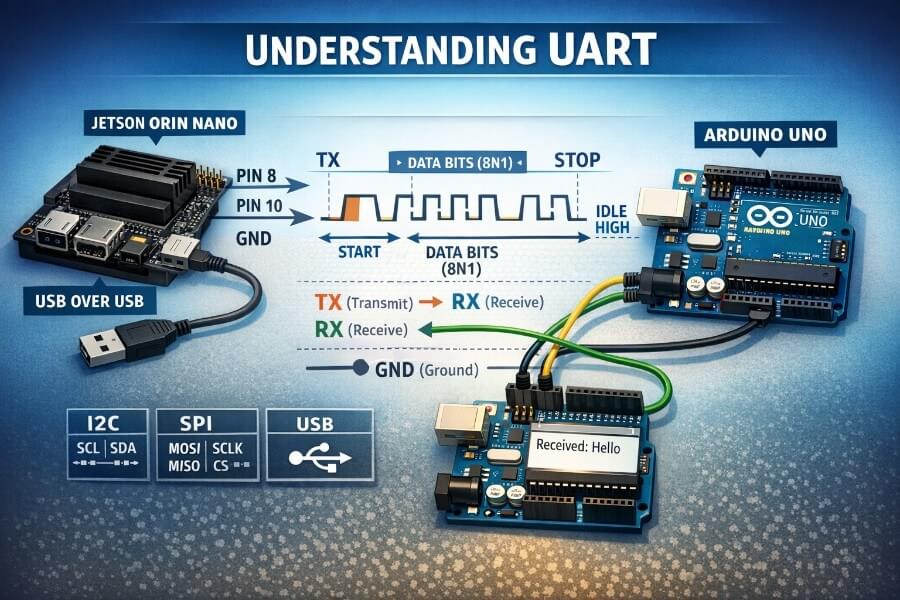
1) The physical layer: the wires and what RX/TX mean
The minimal wiring (3 connections)
A minimal UART link is:
TX: Transmit (output)
RX: Receive (input)
GND: Ground (reference)
You must cross TX and RX:
Device A TX  --->  Device B RX
Device A RX  <---  Device B TX
GND           ---  GND
RX vs TX (the common beginner confusion)
TX is “what I send out”
RX is “what I listen to”
So your TX must go to the other device’s RX.
2) The protocol basics: how bytes are encoded (Start/Stop bits)
UART sends bytes as a stream of bits, with framing so the receiver can find where a byte begins and ends.
Idle state
UART line is typically idle high (logic 1).
Start bit + data bits + optional parity + stop bit(s)
The common format is 8N1:
8 data bits
N = no parity
1 stop bit
So for each byte:
start bit = 0
8 data bits (LSB first)
stop bit = 1
Visually:
Idle Start b0 b1 b2 b3 b4 b5 b6 b7 Stop Idle 1 0 . . . . . . . . 1 1
3) Baud rate: the “speed” setting both sides must match
UART is asynchronous, so both sides must agree on:
baud rate (e.g., 115200)
frame format (8N1, etc.)
If baud rates don’t match, you’ll see:
garbled characters
random symbols
missing bytes
Common baud rates:
9600 (slow, legacy)
115200 (very common)
1,000,000+ (possible but more sensitive to wiring/noise)
4) Optional extra lines: RTS/CTS (hardware flow control)
Besides TX/RX, some UART setups use flow control:
RTS (Request To Send): “I want to send; are you ready?”
CTS (Clear To Send): “Yes, go ahead.”
This prevents overflowing small buffers at higher speeds.
In hobby robotics and quick prototypes, you often use TX/RX only (no RTS/CTS). But it’s good to know what those labels mean on pin maps.
5) UART in robotics and cyber-physical systems: when to use it
UART is a great fit when:
you need a simple, reliable point-to-point link
you want to debug easily
latency matters but bandwidth doesn’t have to be huge
you control both ends of the protocol
Typical use cases:
sending commands to a motor controller (text or binary protocol)
reading GPS NMEA sentences
debugging a microcontroller
bridging between a high-level SBC (Jetson) and low-level MCU (Arduino/STM32)
6) Alternatives to UART (and when they’re better)
In robotics/CPS, you’ll also see:
I²C
2 wires (SDA/SCL) + GND
good for sensors
multiple devices on the same bus
shorter distance, more sensitive to noise
SPI
faster than I²C/UART
more wires (MOSI/MISO/SCLK/CS…)
great for high-speed peripherals (IMUs, ADCs, displays)
CAN / CAN-FD
designed for noisy environments
message arbitration, robust
common in automotive and serious robotics
RS-485 (often “UART over differential”)
long distances
very noise resistant
multi-drop networks
common in industrial environments
Ethernet
scalable, high bandwidth
heavier stack
good for distributed robots / multi-computer systems
USB
plug-and-play convenience
also heavier stack
often used for dev tools, cameras, serial adapters, MCUs
Part 2 — UART on Jetson Orin Nano (JetPack 6.x)
Jetson boards expose multiple serial controllers. In Linux, they typically appear as /dev/ttyTHS* (Tegra High Speed UART) or /dev/ttyS* depending on configuration.
You already confirmed on your system that the kernel registers UART devices like ttyTHS1 and ttyTHS2.
7) Safety first: voltage levels (critical)
Jetson header UART is 3.3V logic
Jetson GPIO/UART pins on the 40-pin header are 3.3V.
Arduino Uno is 5V logic
Directly wiring Arduino Uno TX/RX pins to Jetson header UART can damage the Jetson (5V into a 3.3V input).
Safe options:
Use a USB↔UART 3.3V adapter (FTDI/CP2102/CH340 configured for 3.3V)
Use a 3.3V microcontroller (ESP32, STM32, etc.)
Or use Arduino Uno over USB (recommended for beginners)
8) Method A — Using Jetson’s 40-pin header UART (Pins 8 and 10)
8.1 Identify the pins
On Jetson’s 40-pin header (Raspberry Pi style):
Pin 8: UART TX (Jetson transmits)
Pin 10: UART RX (Jetson receives)
(Exact naming can vary by carrier board / JetPack settings, but pin 8/10 are the classic UART pair you tested.)
8.2 Check that the kernel sees UART controllers
Command
sudo dmesg | grep -i uart
What it does:
Reads the kernel ring buffer and filters lines containing “uart”. You should see drivers and serial devices being registered.
You also checked:
sudo dmesg | grep -i ths
What it does:
Filters for ttyTHS* devices. On your system you saw lines like:
ttyTHS1 ... is a TEGRA_UARTttyTHS2 ... is a TEGRA_UART
8.3 Check device files exist
ls -l /dev/ttyTHS*
What it does:
Lists the character devices exposed by the kernel.
Typical output might include:
/dev/ttyTHS1/dev/ttyTHS2
8.4 Permissions: allow a normal user to access serial devices
Linux usually restricts serial devices to group dialout.
Add your user to dialout
sudo usermod -aG dialout $USER
What it does:
usermod: modifies a user account-aG dialout: append (-a) user to supplementary group (-G)dialout$USER: your current user
✅ You must log out and back in for this to take effect.
Check:
groups
8.5 Validate pin configuration (optional but useful)
You tried:
sudo cat /sys/kernel/debug/pinctrl/2430000.pinmux/pins | grep uart1
What it does:
Reads pinmux debug state (which pins are assigned to which functions)
Filters for “uart1”
If nothing prints, it can mean:
different naming on your platform
a different UART block is mapped
the debug info doesn’t label it the way you expect
This isn’t always necessary if your end-to-end test works, but it’s good for deeper debugging.
8.6 Test UART with a loopback wire (TX ↔ RX)
This is the simplest test because it requires no external device.
Wiring
Physically connect:
- Pin 8 (TX) to Pin 10 (RX)
This is safe because you connect an output to an input.
Why loopback works
Anything transmitted from TX comes right back into RX, so the system “hears itself”.
8.7 Loopback test with minicom
Install
sudo apt install -y minicom
What it does:
- Installs a serial terminal program (like a “terminal for UART”).
Open the port
Try one device (example):
minicom -D /dev/ttyTHS1 -b 115200
What it does:
-D: which serial device to open-b: baud rate
“Nothing happens when I type”
That’s common. Two reasons:
Minicom may not show your keystrokes by default (no local echo)
Some terminals buffer until Enter depending on settings
Enable local echo in minicom
Inside minicom:
- Press
Ctrl + A, thenE
Now you should see what you type locally, and with loopback you’ll see echoed data too.
8.8 Loopback test with stty + cat (more “Linux-native”)
This is what you used successfully and it’s great for understanding what’s happening.
Configure the serial port
sudo stty -F /dev/ttyTHS1 115200 raw -echo
What it does:
stty: configures terminal/serial settings-F /dev/ttyTHS1: apply settings to that device file115200: baud rateraw: raw mode (no line processing)-echo: disable local echo
Terminal 1: read from UART
sudo cat /dev/ttyTHS1
What it does:
- Blocks and prints any bytes arriving on RX.
Terminal 2: write to UART
echo "HELLO" | sudo tee /dev/ttyTHS1
What it does:
echo "HELLO"produces bytesteewrites them into the deviceWith TX ↔ RX loopback, you’ll see
HELLOin Terminal 1
8.9 If it doesn’t work: “Is the port used as a console?”
On many embedded boards, one UART may be used as a kernel console.
Check kernel command line:
cat /proc/cmdline | grep -i console
What it does:
- Shows how the kernel was booted and whether it uses a serial console like
console=ttyTHS1.
If you see that, the UART may be “busy” for console logs.
You can still sometimes use it, but it may interfere with your data. If you plan to use the header UART for robotics comms, you typically want a UART not used by the system console.
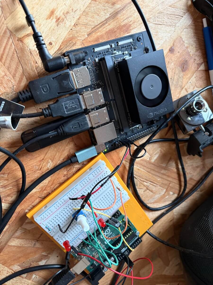
Part 3 — UART via USB with Arduino Uno (the beginner-friendly path)
This is the method you already got working and it’s the best “safe default”.
9) Key idea: it’s not the header UART anymore
When you plug Arduino Uno via USB, Linux exposes a serial device like:
/dev/ttyACM0(very common for Uno)sometimes
/dev/ttyUSB0(for USB-serial adapters)
This is still “serial/UART-like” from your perspective, but physically it’s going through USB.
Important consequence:
You do not need pins 8/10 for this link.
You avoid 5V/3.3V wiring risks.
10) Step-by-step: Arduino Uno code (echo server)
Upload this to Arduino:
void setup() {
Serial.begin(115200);
Serial.println("Arduino ready");
}
void loop() {
if (Serial.available()) {
String msg = Serial.readStringUntil('\n');
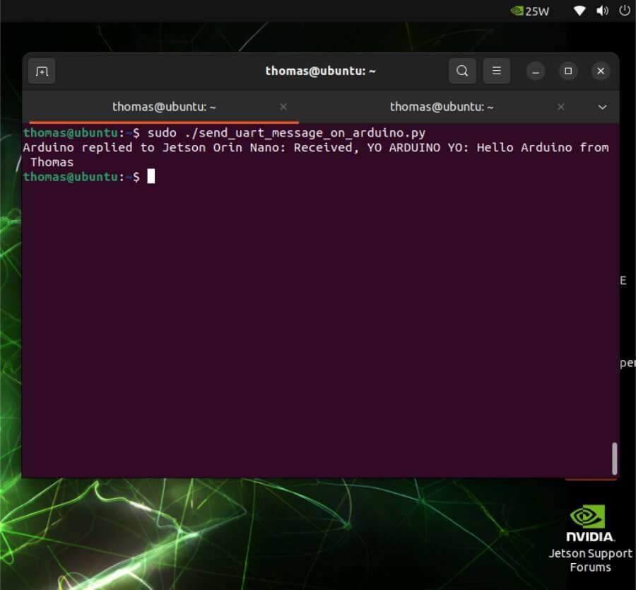
Serial.print("Received YO ARDUINO YO: ");
Serial.println(msg);
}
}
What it does:
Opens serial at 115200
Prints a “ready” line
Waits for a line ending
\nEchoes it back
11) Jetson side: find the device
Plug Arduino Uno into the Jetson via USB, then:
ls /dev/ttyACM*
If you see:
/dev/ttyACM0
Great.
If not:
dmesg | tail -n 50
What it does:
- Shows recent kernel messages (USB device attach events, driver binding, etc.)
12) Quick test with minicom
minicom -D /dev/ttyACM0 -b 115200
Type:
hello
Press Enter.
Expected:
Received: hello
13) Python tutorial: sending text to Arduino with pyserial
You installed:
sudo apt install -y python3-serial
That installs the serial module for Python 3.
Common beginner mistake (you hit it)
Typing Python code directly into Bash:
thomas@ubuntu:~$ import serial
bash: import: command not found
Bash is a shell; import is a Python keyword. You must run python3 or a .py script.
13.1 Create a python file (recommended)
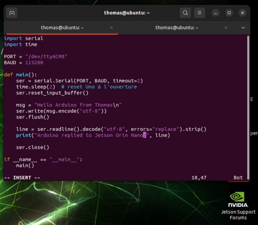
Create and update text:
nano send_to_arduino.py
Paste:
#!/usr/bin/env python3
import serial import time

PORT = "/dev/ttyACM0"
BAUD = 115200
def  main():
    ser = serial.Serial(PORT, BAUD, timeout=2) # Arduino Uno often resets when opening the port (DTR toggling).
    time.sleep(2) # Remove any boot message from the buffer.
    ser.reset_input_buffer()

    msg = "Hello Arduino from Thomas\n"
    ser.write(msg.encode("utf-8"))
    ser.flush()

    line = ser.readline().decode("utf-8", errors="replace").strip()
    print("Arduino replied to Jetson Orin Nano:", line)

    ser.close() if __name__ == "__main__":
    main()
Run:
chmod +x send_to_arduino.py
./send_to_arduino.py
Part 4 — When would you actually use pins 8/10 in a robot?
Pins 8/10 (header UART) become valuable when you want:
fewer cables / no USB stack
predictable behavior at boot
a dedicated MCU link inside your robot chassis
a UART device that stays stable even if USB devices reorder
In “production-ish” robotics:
Jetson <-> MCU via UART header is common
but you usually pick a 3.3V MCU or use a level shifter
Part 5 — Cheat sheet
Header UART (pins 8/10)
Device likely:
/dev/ttyTHS1or/dev/ttyTHS2Test loopback:
wire pin 8 ↔ pin 10
use
minicomorstty/cat
Commands:
sudo dmesg | grep -i ths
ls -l /dev/ttyTHS*
sudo  stty -F /dev/ttyTHS1 115200 raw -echo
sudo  cat /dev/ttyTHS1
And in another terminal:
echo "HELLO" | sudo tee /dev/ttyTHS1
Arduino Uno over USB
Device:
/dev/ttyACM0Test:
ls /dev/ttyACM*
minicom -D /dev/ttyACM0 -b 115200
python3 send_to_arduino.py
Final notes: the “beginner mistakes” that are totally normal
Forgetting to cross TX/RX
Forgetting to connect GND (for wired UART)
Mixing 5V and 3.3V UART (danger)
Typing Python into Bash
“Nothing prints” because the terminal doesn’t echo by default
Conclusion: UART as a Foundation, Not a Limitation
UART is often introduced as a “simple” or “legacy” protocol. After working through both the theory and hands-on experiments on the Jetson Orin Nano, it becomes clear that this simplicity is precisely its strength.
By understanding how UART actually works at the electrical and framing level, you gain more than the ability to send text between two boards:
you gain intuition about timing, buffers, and asynchronous communication
you understand why debugging over serial is still the first tool engineers reach for
you learn how Linux exposes hardware peripherals as file-like interfaces
you see how a high-level system (Jetson) can reliably cooperate with a low-level controller (Arduino)
In this article, we explored two complementary approaches:
Header UART (pins 8 & 10)
This is the embedded-native way. It is ideal when building a robot or cyber-physical system where the Jetson is permanently integrated, wiring is fixed, and you want predictable behavior from boot to shutdown. This approach forces you to think about voltage levels, pin multiplexing, and kernel configuration—key skills for real-world robotics.UART over USB with Arduino Uno
This is the developer-friendly path. It trades a bit of abstraction for safety, convenience, and speed of iteration. For prototyping, testing ideas, and learning, this method is often the smartest choice. It also mirrors how many professional tools (debug probes, GPS modules, motor controllers) present themselves to Linux systems.
Crucially, UART should not be seen in isolation. In robotics and cyber-physical systems, it often plays a specific role:
as a control channel between compute and actuation layers
as a debug and observability channel
as a reliable fallback when higher-level networks fail
As systems grow, UART is frequently complemented, not replaced, by protocols such as CAN, SPI, or Ethernet. But the mental model you build here carries over directly: framing, flow control, latency, determinism, and failure modes.
If you are working on robots, embedded AI systems, or cyber-physical platforms, mastering UART is not about nostalgia, it is about building intuition at the boundary between software and hardware. That intuition will continue to pay dividends long after you move on to more complex buses and stacks.
In the next steps, this foundation naturally leads to:
designing a simple command protocol on top of UART
adding acknowledgments, timeouts, and error handling
separating high-level decision-making (Jetson) from low-level real-time control (microcontroller)
UART is not the end of the story, but it is one of the best places to begin.