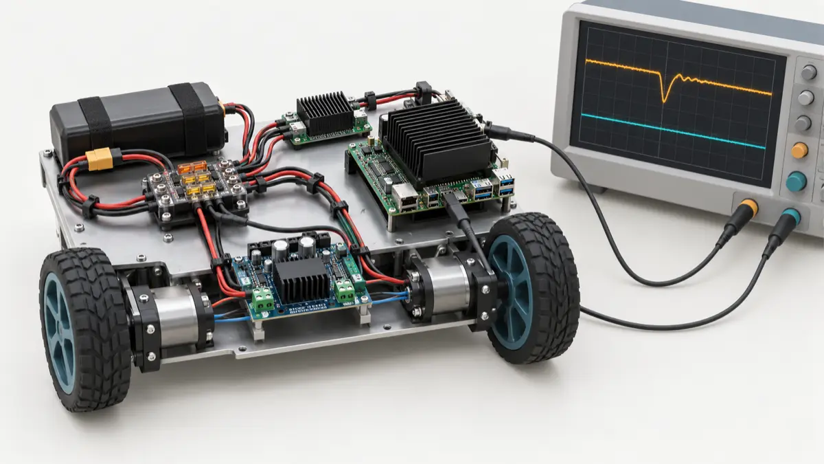
A robot runs its perception model correctly on the bench. Once the wheels accelerate, the camera disappears, inference latency jumps, or the Jetson reboots. The failure lands in the software team’s queue because that is where the symptoms are visible. Yet a new model, a ROS 2 QoS change, or a longer watchdog timeout cannot repair a collapsing supply rail.
To diagnose this class of failure, measure voltage at the consuming device while recording motor current, compute load and reset events. Separate sustained power demand from short load steps, and test braking as well as acceleration. A supply’s wattage rating alone does not establish whether the robot’s compute and sensor rails remain usable through those events.
The central engineering question is: can the electrical system preserve the operating conditions assumed by the AI and control software, including when several loads change together? The useful deliverable is a power-domain map with measured limits and a reproducible fault test, not just a larger battery.
The examples below describe an illustrative low-voltage mobile robot. All numerical loads and waveforms are design exercises, not measurements from a deployed machine. Component ratings, wiring, protection and motion tests must be qualified for the actual hardware.
Follow the power path to the load
Start with the battery or supply, then draw every protection device, connector, converter and return path between it and the load. Include the carrier board, USB peripherals, storage, fan and motor-driver logic. A module power mode is only one input to this drawing.
The distinction between carrier input and module supply matters. NVIDIA’s Orin Nano developer-kit carrier specification, revision 1.3, describes a DC-jack input and an onboard regulator supplying the module. Those are different electrical nodes. Check the specification for your exact carrier and revision; a voltage valid at its input connector is not permission to apply that voltage to a module pin or expansion header.
Use a map like this as a review artifact. The branch names are examples; the limits must come from your design.
| Power domain | Measurement point | Contract to establish |
|---|---|---|
| Shared rail | Source terminals and distribution input | Loaded voltage range, total pulse current, protection trip behavior |
| Compute | Converter input and carrier power connector | Allowed input range, load-step droop, startup and recovery |
| Sensors | Camera or hub connector | Voltage during simultaneous startup, cable loss, reset behavior |
| Motor drive | Motor-driver supply pins | Acceleration demand, bus rise during braking, current limiting |
| Control | MCU supply and driver enable interface | Behavior when compute, motor power or the MCU itself disappears |
For each row, record an owner, probe location, load scenario, minimum and maximum permitted voltage, event duration, and the evidence file that demonstrates compliance. Use recommended operating limits and protection behavior, not absolute-maximum ratings as normal operating targets.
Separately regulated compute and motor branches can reduce coupling. They still share a failure path if the same battery, connector, fuse or upstream wiring collapses. Nor does separate regulation imply galvanic isolation. Keep high-current motor returns out of sensitive signal-return paths, and preserve the electrical reference required by non-isolated interfaces. The CAN/UART/I2C/SPI architecture decision must agree with the grounding and harness design.
Budget coincident events, not a sum of average watts
A useful budget has at least three operating cases: sustained mission load, startup, and the worst credible overlap of load changes. Add a separate energy-return case for braking.
Consider an illustrative robot with a nominal 24 V source. At a low-voltage operating point of 20 V at the branch inputs, assume:
- A regulated 12 V compute branch delivers 36 W to its complete load at 90% converter efficiency.
- A sensor branch delivers 10 W at 85% efficiency.
- Each of two motor drives draws a 6 A pulse from the bus for 100 ms during the chosen acceleration event.
The approximate coincident input current is:
1 | Compute: 36 W / (20 V × 0.90) = 2.00 A |
The motor numbers are bus currents, not phase currents or a driver’s headline current rating. PWM operation and current regulation make those different quantities. Use measured bus demand or a justified drive model, including the configured current limit. Do not reproduce a stall on an unconstrained robot merely to obtain a number.
At 14.59 A, a shared supply-and-return path with 0.12 ohm total resistance drops approximately 1.75 V. That is a screening calculation: the load current changes with voltage, converter efficiency and protection state. Recalculate the operating point with the source impedance and wiring included. A regulated constant-power load tends to draw more input current as its input voltage falls, until it reaches a limit or shuts down.
This is why a nominally adequate supply can fail only near the end of a mission. The converter must tolerate the actual low input voltage and still deliver the output load within its thermal and current limits. The battery protection, connectors and wiring must also tolerate the pulse. A fuse rating is not a promise that a 100 ms event will pass; inspect the relevant time-current behavior and electronic protection thresholds.
Treat inference startup as an electrical event too. Record whether the test overlaps camera startup, model loading, GPU activity, storage writes and acceleration. Testing each subsystem in isolation leaves the coincidence assumption untested.
A capacitor must cover a measured charge deficit
“Add a capacitor” is incomplete advice. First determine which rail dips, how much current the upstream supply fails to provide, and for how long.
For a simplified constant deficit, the ideal capacitance is:
1 | C ≥ I_deficit × duration / allowed_droop |
Suppose the compute rail has a 2 A deficit for 2 ms and can spare 0.4 V of droop. The ideal result is 0.01 F, or 10,000 µF. A 470 µF capacitor would cover that same deficit for only 94 µs, before accounting for parasitics. These numbers show the scale of the problem; they are not a component recommendation.
The instantaneous resistive drop also consumes the voltage allowance. At 2 A, 0.05 ohm ESR costs 0.1 V immediately. Only 0.3 V remains for charge depletion, increasing the simplified requirement to about 13,300 µF. Inductance adds another fast transient. Analog Devices’ load-transient analysis explains the ESR and ESL contributions; the arithmetic here uses separate illustrative inputs.
For a real waveform, integrate the positive current deficit over time. Then check effective capacitance at bias and temperature, ripple-current capability, regulator stability and startup inrush. Increasing capacitance can move the failure from acceleration to power-on if the charging current trips upstream protection.
Use the diagnosis to choose the intervention. A resistive connector needs repair or redesign. A converter entering current limit needs a different operating envelope or supply design. Fast local noise needs layout and decoupling work. Milliseconds of missing energy may require substantial storage, a different converter, or a reduction in coincident demand.
Braking can push the bus upward
Acceleration tests find supply droop. Braking tests can reveal the opposite problem: mechanical energy returns through the drive and raises the DC bus voltage. Whether it does so, and by how much, depends on the motor, drive topology and braking mode.
Texas Instruments’ motor-drive electrical-overstress guidance discusses voltage margin, bulk capacitance and transient suppression. The practical design question is where returned energy can go. Check the supply’s sinking capability and the battery/BMS charge-acceptance conditions, including a full battery or an opened protection path.
As an idealized bound, assume 0.5 J reaches a 1,000 µF bus capacitor initially at 24 V, with no other energy sink:
1 | E = ½ C (V_after² − V_before²) |
This is an energy-conservation calculation, not a prediction of a particular drive. It shows why a small capacitor cannot be assumed to absorb an arbitrary braking event. The actual design may need a qualified regenerative path or braking resistor/chopper arrangement. Size any clamp for voltage, pulse energy and repetition rate; a transient suppressor is not automatically a continuous braking-energy sink.
Do not infer that cutting motor power always produces the required stop. Some mechanisms need powered braking or a holding brake. Tie the power-loss behavior back to the machine’s stop and failsafe architecture.
Distinguish rail faults from software symptoms
Capture the electrical event and the software consequence on a shared timeline. Measure at the device connector, not only at the bench supply. When channels permit, capture the source and load simultaneously: a stable source with a collapsing load rail points the investigation downstream.
Use probes appropriate to the circuit and voltage, short measurement loops, and a differential probe where the reference requires it. Bench-scope ground clips are commonly earth-referenced; attaching one to a switching node can create a short. Secure the robot and use a controlled load fixture for fault tests before testing motion.
The minimum useful capture combines:
- Compute-connector voltage and motor-bus voltage/current, with pre-trigger history.
- A timestamped marker for the commanded load transition, with its software-to-instrument timing uncertainty documented.
- GPU/CPU clocks, temperatures, power mode and inference latency.
- Kernel device-disconnect events, MCU reset causes and host boot identity.
NVIDIA’s Jetson Linux r36.5 power-management guide documents undervoltage, average-overcurrent and instantaneous-overcurrent events, together with monitoring and throttling behavior. Read the counters and tools supported by the deployed BSP; do not assume a hard-coded hardware-monitor index applies to every board. A throttling notification alone does not identify which connector, regulator or workload caused it.
Software telemetry is useful context, but its sampling rate can miss a short rail disturbance. An uneventful dashboard cannot rule out a sub-millisecond dip. Preserve instrument captures with the ROS logs and rosbag evidence, linked by run ID and trigger marker.
| Observation | Next discriminating check |
|---|---|
| Whole host reboots at acceleration | Compare source, converter input and carrier input; inspect reset and protection evidence |
| Only the USB camera disconnects | Probe its local supply and hub path; also check cable and host-controller errors |
| Inference slows without a reboot | Correlate clocks, temperature and power events with voltage; then inspect CPU/GPU contention |
| MCU resets while the Jetson survives | Probe the MCU rail and reset pin; inspect return-path coupling and local regulation |
| Fault occurs during deceleration | Trigger on bus overvoltage and inspect the energy-return path |
| Serial errors track motor switching with stable average voltage | Examine fast noise, references and routing before changing protocol timeouts |
None of these symptoms proves an electrical cause by itself. Change one variable, repeat the trigger, and preserve both failing and passing traces.
For brushed motors, Pololu’s motor-noise application note describes brush-generated interference, local suppression and separation of motor wiring from signal wiring. That is a useful mechanism-specific reference. Apply the motor and drive manufacturer’s recommendations; do not copy a brushed-motor capacitor arrangement indiscriminately onto a different drive topology.
Qualify the transition and the recovery
Turn the diagnosis into a repeatable bench plan. Define voltage envelopes and permitted behavior before running it, so “the robot did not reboot this time” is not the acceptance criterion.
| Test case | Evidence required |
|---|---|
| Inference load step with motors disabled | Compute rail stays within its specified envelope; latency and throttling remain within the workload contract |
| Motor pulse with compute idle | Shared-path drop and motor interference remain within the declared limits |
| Worst permitted overlap at low source voltage | No unexpected protection trip, device reset or sensor loss |
| Braking with least available energy absorption | Bus remains below design limits; the energy sink stays within its ratings |
| Controlled supply dip on a restrained fixture | Reset and actuator behavior match the declared fault response |
| Power restoration after the dip | Devices reinitialize, stale commands are rejected and motion authority is re-established deliberately |
Repeat relevant cases across the approved battery state, temperature, cable configuration and peripheral set. Record pulse width, repetition rate and load slew rate: two tests with the same peak current can stress the system differently. Specify capture bandwidth and sampling, and retain the waveform rather than only its displayed minimum.
Recovery deserves its own acceptance condition. A surviving MCU may still hold the last command when the Jetson restarts. A rebooted camera may appear under a different device path. The software boundary must identify the new session, invalidate old authority and verify fresh sensor state before resuming. The existing microcontroller/Jetson responsibility split provides the control architecture; the power test establishes whether it behaves as intended when one side loses power.
For release, keep the schematic and harness revision, exact carrier/BSP configuration, converter settings, load profiles, probe setup, traces, reset evidence and acceptance results together. Re-run affected cases when a model changes compute demand, a peripheral is added, a cable changes, or a drive’s acceleration/current limit is raised.
The repair is complete when the team can reproduce the original electrical stress, show the rails remain within their contracts or enter the specified fault response, and demonstrate controlled recovery. That evidence gives the software team a power system it can actually depend on.